Supercharge Your Innovation With Domain-Expert AI Agents!

Pneumatic cylinder group

A pneumatic cylinder and air cylinder technology, applied in the direction of fluid pressure actuation device, etc., can solve the problems of adjustment and control of the moving speed of the piston and piston rod, and the time delay of returning to the original state, etc.

Active Publication Date: 2020-09-04
威海新安精密机械有限公司
View PDF8 Cites 0 Cited by
  • Summary
  • Abstract
  • Description
  • Claims
  • Application Information

AI Technical Summary

Problems solved by technology

[0006] First, when the operation stops, the recovery time will be greatly delayed due to the residual compressed air left inside;
[0007] Second, it is difficult to adjust and control the moving speed of the piston and the piston rod at the desired level as required

Method used


Image

  • Pneumatic cylinder group
  • Pneumatic cylinder group
  • Pneumatic cylinder group

Examples


Embodiment Construction

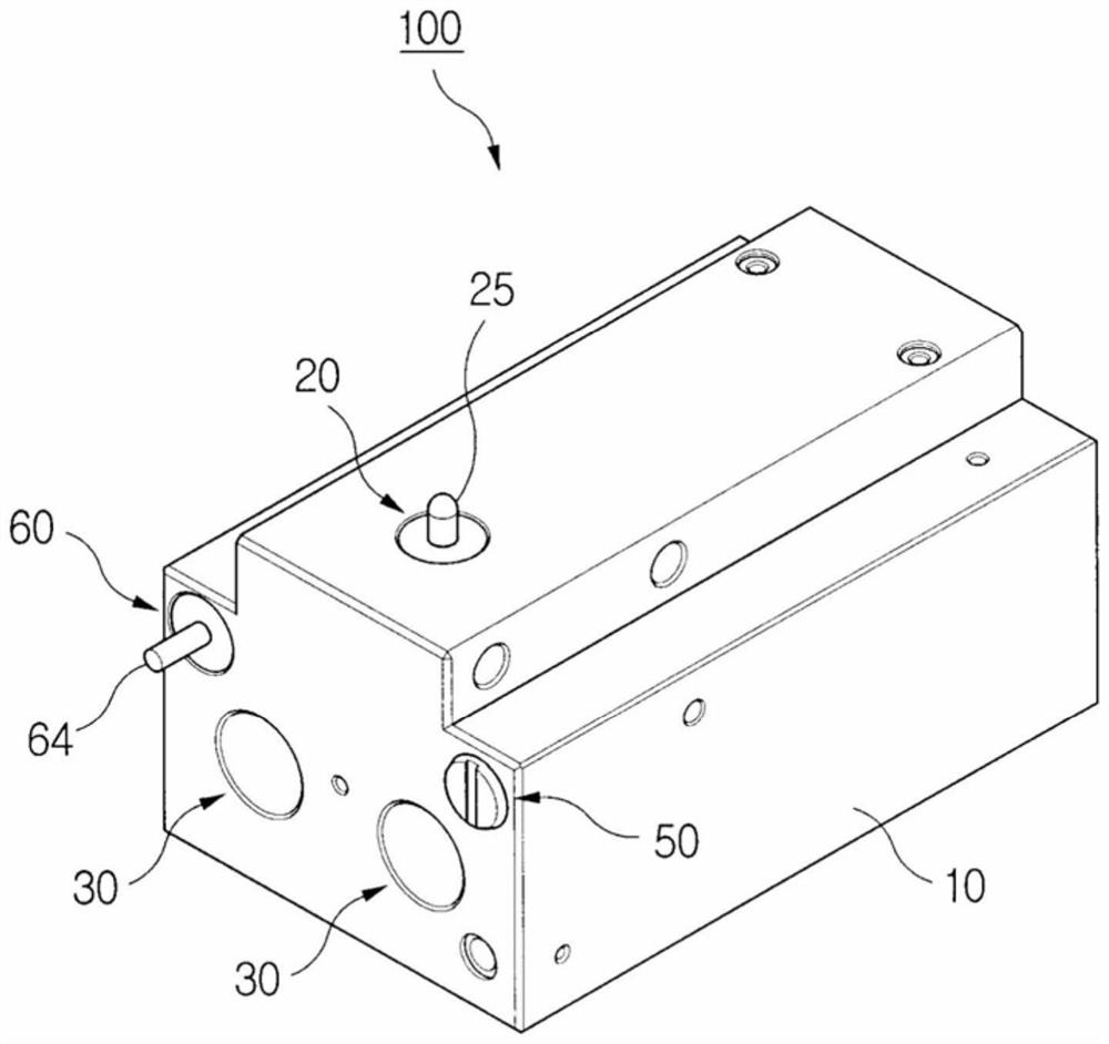
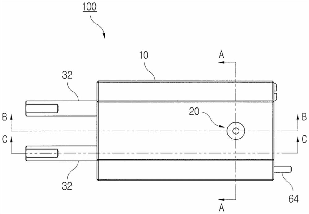
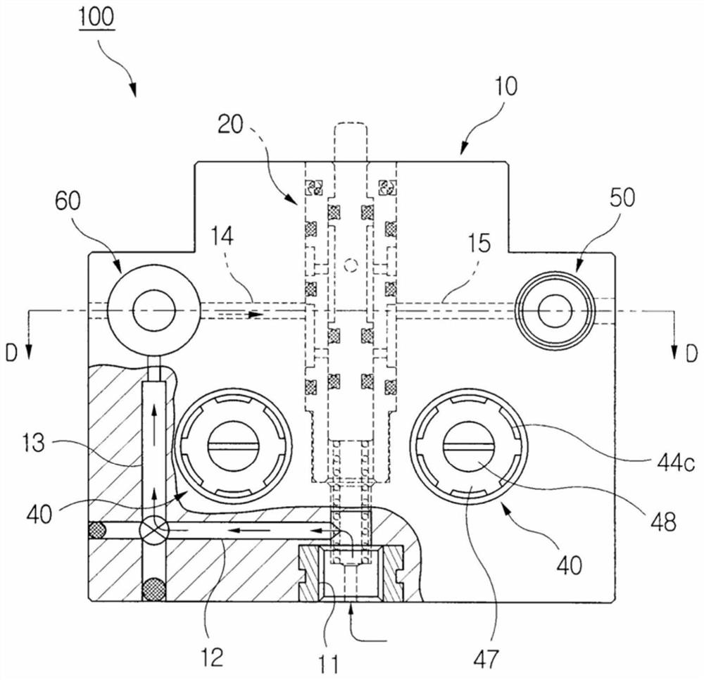
[0044] The features and effects of the "pneumatic cylinder group (hereinafter referred to as cylinder group)" of the present invention described and not described above will become more clear from the description of the embodiments described below with reference to the accompanying drawings. The cylinder bank according to the invention is identified with the symbol "100" in the individual figures.

[0045] The cylinder block 100 of the present invention includes: a reinforced plastic block-type main body 10; a compressed air injection port 11 organically formed and arranged inside the main body 10 by processing the main body 10; a control part 20; a cylinder part 30; a valve part 40; part 50; and release part 60. The injection port 11 is formed in front of the lower surface of the main body 10 . Here, the compressed air inlet 11 is configured as a single unit.

[0046] Said control part 20 comprises: a switching device 21 arranged on the main body 10 to allow the supply of c...


PUM


Abstract

The invention relates to a pneumatic cylinder group. The pneumatic cylinder group comprises a compressed air injection port formed in a blocky main body organically, a control part permitting compressed air to supply, cylinder parts operated depending on the compressed air, valve parts used for regulating the moving speed of pistons of the cylinder parts, and a discharge part used for dischargingthe compressed air in the main body outwards. Particularly, the cylinder group further comprises a relief part used for enabling the cylinder parts to quickly reset through operation of spools, and each valve part is a two-stage air control valve comprising a check valve and a screw valve which are arranged in series. According to the pneumatic cylinder group provided by the invention, the cylinder parts are operated according to the limited and regulated speed, and can be quickly reset when stopping.

Description

technical field [0001] The present invention relates to a pneumatic cylinder, and more particularly, to a pneumatic cylinder group used as a clamping device for a jig for electronic component inspection. Background technique [0002] "Pneumatic cylinder" in the general sense refers to a cylinder device that converts the energy of compressed air supplied at high speed into mechanical reciprocating linear motion. Specifically, under the action of compressed air, the piston and the rod reciprocate, and at the same time move the object supported on one end thereof. Generally speaking, this kind of pneumatic cylinder plays the same role when the piston rod advances and retreats, and its advance and retreat are all completed by the compressed air injected and supplied separately. [0003] Therefore, the operation of the cylinder not only consumes a large amount of compressed air unnecessarily, but also complicates the design of the cylinder device. In addition, the functions of ...

Claims


Application Information

Patent Timeline
IPC IPC(8): F15B15/14F15B15/20
CPCF15B15/1423F15B15/20
Inventor 黄河春
Owner 威海新安精密机械有限公司
Features
  • R&D
  • Intellectual Property
  • Life Sciences
  • Materials
  • Tech Scout
  • Unparalleled Data Quality
  • Higher Quality Content
  • 60% Fewer Hallucinations
Learn More