
A dual-chamber annular micro-combustor based on Swiss roll structure

A micro-burner and annular technology, which is applied in the direction of burner, gas fuel burner, combustion type, etc., can solve the problems of reduced heat release of fuel, shortened fuel residence time, and low combustion efficiency, so as to reduce the ignition time. Effects of requiring energy, shortening ignition delay time, and improving flame stability

Active Publication Date: 2021-07-27
HUAZHONG UNIV OF SCI & TECH
View PDF9 Cites 0 Cited by
  • Summary
  • Abstract
  • Description
  • Claims
  • Application Information

AI Technical Summary

Problems solved by technology

[0003] However, the current micro-combustion faces the following problems: (1) The residence time of the fuel is short - as the characteristic length scale of the burner decreases, the high flow rate makes the residence time of the fuel shorten, especially when the residence time of the components When approaching the characteristic combustion time, the incomplete combustion of the fuel reduces the heat release and increases the heat loss, which makes it difficult for the flame to sustain itself, and even flameout occurs
(2) Large heat loss - the high specific surface area of ​​the micro-burner causes serious heat loss, and it is prone to hot eaves fire and free radical fire
(3) Low combustion efficiency - the residence time of chemical reaction components is short, which is basically the same order of magnitude as the chemical reaction time of hydrocarbons / air, which easily leads to low combustion efficiency

Method used


Image

  • A dual-chamber annular micro-combustor based on Swiss roll structure
  • A dual-chamber annular micro-combustor based on Swiss roll structure
  • A dual-chamber annular micro-combustor based on Swiss roll structure

Examples


specific Embodiment

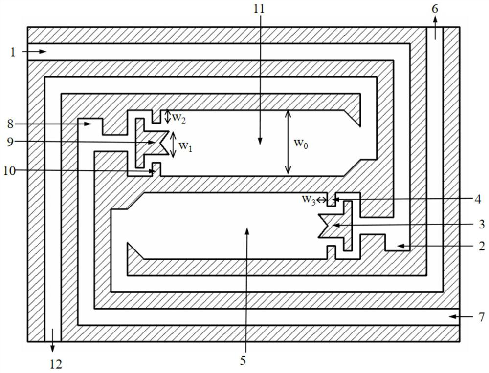
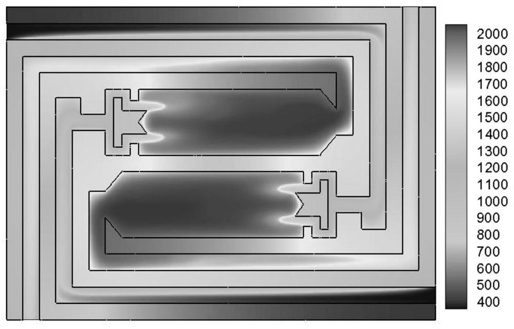
[0032] The methane and air adopt the micro-burner of the pre-mixed combustion method in advance; 0 = 4mm, W 1 = 1.4mm, W 2 = 0.7mm, W 3 =0.5mm; the length of the micro burner is 26mm, the width is 19mm, the solid material is steel, and its density, heat capacity, thermal conductivity and normal emissivity are respectively 8000kg / m 3 , 500J / (kgK), 24W / (m 2 K) and 0.2. Using the fluent numerical simulation method, the detailed methane combustion mechanism (19 steps and 58 primitives) is used to carry out the numerical simulation when the equivalence ratio is 0.5 and the inlet velocity is 10m / s. Such as image 3 As shown, is the cross-sectional temperature field. It can be seen that the gas burns stably in the combustion chamber, the flame anchoring effect is good, and the combustion efficiency can be maintained above 99.5%.


PUM


Abstract

The invention belongs to the technical field of micro-scale power generation, and specifically discloses a double-chamber annular micro-burner based on a Swiss roll structure, which includes a first combustion structure and a second combustion structure, and the first combustion structure includes a first combustion structure connected in sequence. an air passage, a first rectification chamber, a first combustion chamber, and a first exhaust passage; the second combustion structure includes a second intake passage, a second rectification chamber, a second combustion chamber, and a second exhaust passage that are communicated in sequence; A combustion chamber and a second combustion chamber are arranged in reverse symmetry on the upper and lower sides of the center of the micro-burner, so that the inlet end of the first combustion chamber is adjacent to the outlet end of the second combustion chamber, and the outlet end of the first combustion chamber is adjacent to the inlet end of the second combustion chamber Adjacent; the first intake passage is adjacent to the second exhaust passage, and the first exhaust passage is adjacent to the second intake passage. By arranging reverse symmetrical double combustion chambers and annular preheating channels, the invention can reduce the energy required for ignition, shorten the ignition delay time, improve the ignition acceleration limit and widen the inlet speed.

Description

technical field [0001] The invention belongs to the technical field of micro-scale power generation, and more specifically relates to a double-chamber annular micro-combustor based on a Swiss roll structure. Background technique [0002] Combustion of hydrocarbon fuels at the microscale greatly facilitates the application of microelectromechanical systems. The characteristic size of the micro-power system is usually between a few millimeters and a few centimeters. The chemical energy of the fuel is converted into heat energy through the combustion chamber, and then mechanical energy is generated for power generation, and finally electric energy is output. [0003] However, the current micro-combustion faces the following problems: (1) The residence time of the fuel is short - as the characteristic length scale of the burner decreases, the high flow rate makes the residence time of the fuel shorten, especially when the residence time of the components When approaching the ch...

Claims


Application Information

Patent Timeline
Patent Type & Authority Patents(China)
IPC IPC(8): F23D14/26F23D14/46F23D14/66
CPCF23D14/26F23D14/46F23D14/66Y02E20/34
Inventor 马仑方庆艳余圣辉张成陈刚
Owner HUAZHONG UNIV OF SCI & TECH
Learn More