Time-delay fuse

A fuse and outer box technology, applied in the field of time-delay fuses, can solve the problems of inconvenient use of fuses, and achieve the effect of avoiding the risk of manual operation

Inactive Publication Date: 2020-09-04
杨伟
View PDF0 Cites 3 Cited by
  • Summary
  • Abstract
  • Description
  • Claims
  • Application Information

AI Technical Summary

Problems solved by technology

[0004] The purpose of the present invention is to solve the problem of inconvenient use of fuses in the prior art, and propose a time-delay fuse

Method used


Image

  • Time-delay fuse
  • Time-delay fuse

Examples


Embodiment

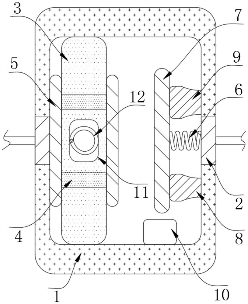
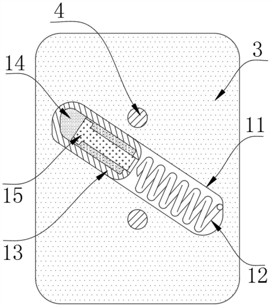
[0018] refer to Figure 1-2 , a time-delay fuse, including an outer box 1, the two symmetrical side walls of the outer box 1 are inserted with a contact piece 2, the inner wall of the outer box 1 is fixed with an adsorption plate 3, and the side wall of the adsorption plate 3 is inserted through A conductive rod 4 is provided, and the two ends of the conductive rod 4 are fixed with a connecting plate 5, the inner wall of the outer box 1 is fixed with a battery 10, and the side wall of the connecting plate 2 far away from the adsorption plate 3 is fixed with a contraction spring 6, and the contraction spring 6 One end close to the adsorption plate 3 is fixed with a conductive plate 7, and the inner wall of the outer box 1 is fixed with a contact block 8 and a limit electromagnet 9 that are against the conductive plate 7. The inside of the adsorption plate 3 is provided with a sliding cavity 11, and the sliding cavity 11 The inner wall is provided with a reset mechanism; the res...


PUM


Abstract

The invention discloses a time-delay fuse. The fuse comprises an outer box, power connection sheets penetrate through and are inserted into two symmetrical side walls of the outer box, and an adsorption plate is fixed to the inner wall of the outer box. A conductive rod is inserted into the side wall of the adsorption plate in a penetrating manner, power connection plates are fixed to the two endsof the conductive rod, and a battery is fixed to the inner wall of the outer box. A contraction spring is fixed to the side wall, away from the adsorption plate, of the power connection plate, and aconductive plate is fixed to the end, close to the adsorption plate, of the contraction spring. The time-delay fuse has the advantages that the conductive plate is in contact with the power connectionplate, an external power utilization circuit is electrified through the connection of the contraction spring, when a fault current of the circuit is increased, the contraction spring can complete contraction action at the moment when the current is increased, so that the conductive plate is separated from the power connection plate, the external circuit is rapidly disconnected, the external circuit and an electric appliance are prevented from being impacted by a high current, and the external circuit and the electric appliance are protected.

Description

technical field [0001] The invention relates to the technical field of fuses, in particular to a time-delay fuse. Background technique [0002] Fuse refers to an electrical appliance that fuses the melt and disconnects the circuit with the heat generated by itself when the current exceeds the specified value; device. [0003] The current fuses mainly include disposable fuses and resettable fuses; once the current disposable fuses are blown, they need to be replaced as a whole, which is very inconvenient, and artificial replacement is very inconvenient, and there are certain safety hazards; The main form of the resettable fuse is a bimetallic strip thermal relay, and its on-off parts are composed of bimetallic strips with different thermal deformation coefficients. When the current is too large and the temperature of the bimetallic strip is too high, the bimetallic strip is deformed due to deformation Disconnect the contact and connect it after cooling down; however, the de...

Claims


Application Information

Patent Timeline
Patent Type & Authority Applications(China)
IPC IPC(8): H01H71/24H01H71/44H01H71/02H01H71/08
CPCH01H71/02H01H71/08H01H71/24H01H71/44
Inventor 杨伟夏春辉陈静
Owner 杨伟
Why Eureka
Try Eureka