Al technical title is built by PatSnap Al team. It summarizes the technical point description of the patent document.
A technology of power cables and connecting devices, which is applied in the field of power cables with connecting devices, and can solve problems such as double clamping of cables that cannot be connected, inability to connect cable connectors, and inability to fix a single set of cables. The effect of stable connection, avoiding bending, and safe use of cable connection
Inactive Publication Date: 2020-09-04
YANGZHOU XUNXIANG CABLE
View PDF10 Cites 1 Cited by
Summary
Abstract
Description
Claims
Application Information
AI Technical Summary
This helps you quickly interpret patents by identifying the three key elements:
Problems solved by technology
Method used
Benefits of technology
Problems solved by technology
[0004] The purpose of the present invention is: in order to solve the problem that the existing cable connectors cannot double-clamp the cables at the joints to fix them inside, and the existing cable connectors cannot be connected to each other, and a single set of cables cannot fixed, and the existing cable connectors cannot protect the connection, reduce the problem of damage near the connection, and provide a power cable with a connection device
Method used
Image
Click on the blue label to locate the original text in one second.
Reading with bidirectional positioning of images and text.
Examples
Embodiment Construction
[0024] The technical solutions in the embodiments of the present invention will be clearly and completely described below with reference to the accompanying drawings in the embodiments of the present invention. Obviously, the described embodiments are only a part of the embodiments of the present invention, but not all of the embodiments. Based on the embodiments of the present invention, all other embodiments obtained by those of ordinary skill in the art without creative efforts shall fall within the protection scope of the present invention.
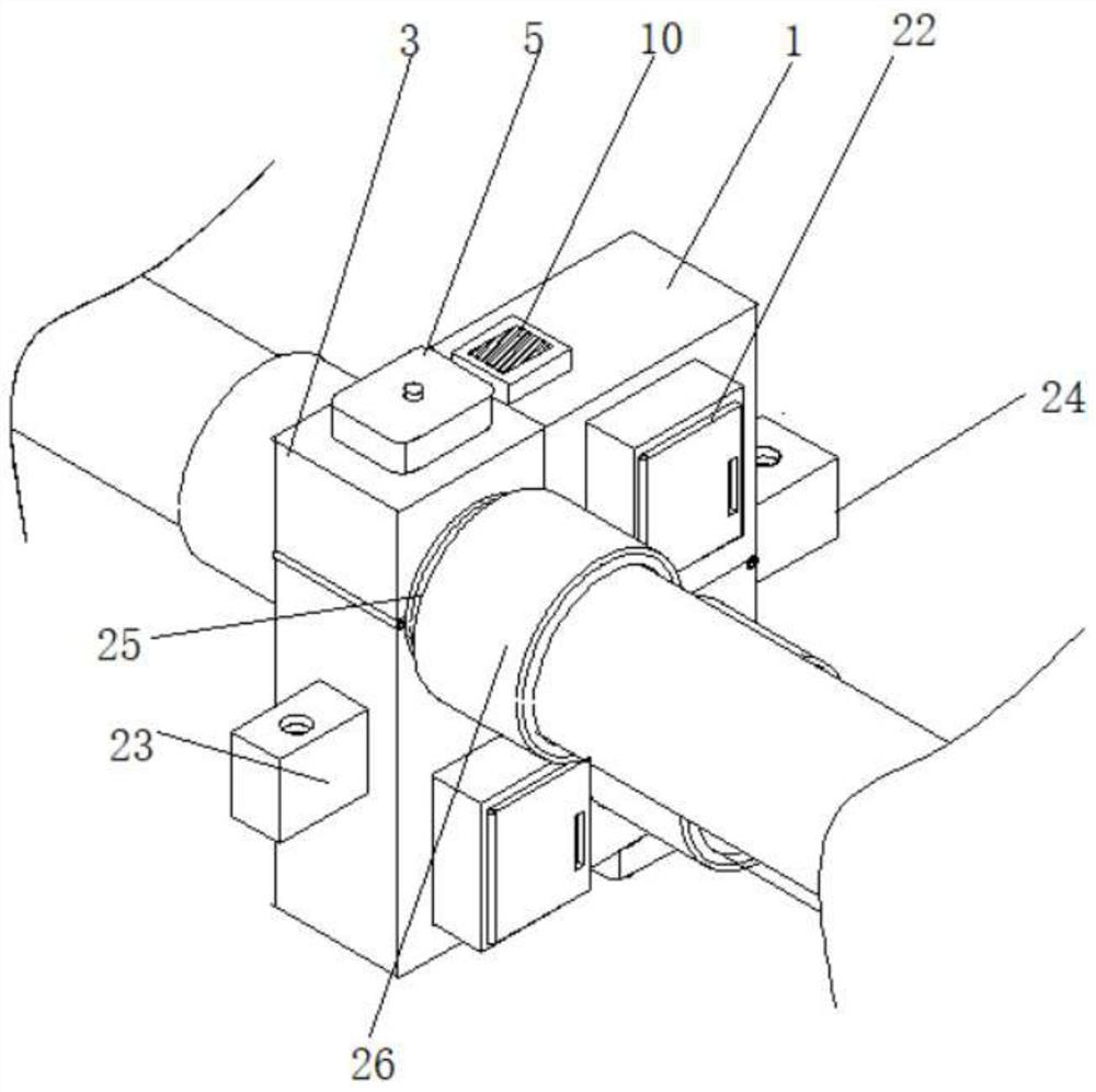
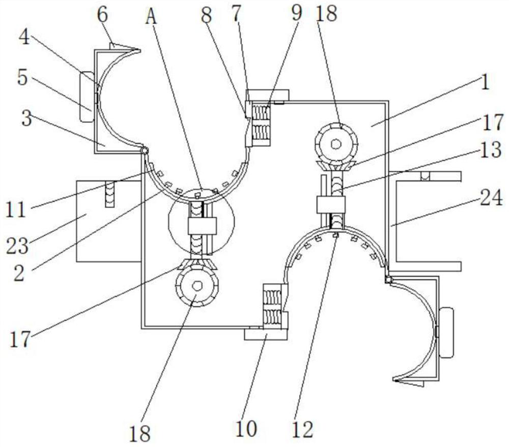
[0025] see Figure 1-5 , a power cable with a connecting device, including a connector body 1, an installation groove 2 is provided inside the connector body 1, and a connection cover 3 is connected to the outside of the installation groove 2, and an air bag 4 is arranged on the inside of the connection cover 3 , and the outer side of the connection cover 3 is provided with a pressing bag 5, and the top end of the installation groove ...
PUM
Abstract
The invention discloses a power cable with a connecting device, relating to the field of power cables. A connecting piece body is included, a mounting groove is formed in the connecting piece body, aconnecting cover is connected to the outer side of the mounting groove, an air bag is arranged in the inner side of the connecting cover, a pressing bag is arranged in the outer side of the connectingcover, an extrusion block is arranged at the top end of the interior of the mounting groove, an extrusion contact is connected to the top end of the extrusion block, and a threaded rod is connected to the bottom end of the extrusion block. The power cable is provided with the connecting piece body, the mounting groove, the connecting cover, the air bag, the pressing bag, the extrusion block, theextrusion contact, the threaded rod, a sleeve rod, a sliding block, a push rod, a first bevel gear, a second bevel gear and a grip, so that a cable connector is arranged between the mounting groove and the connecting cover, the connecting cover can apply pressure to the cable through the air bag to enable the cable to be fixed more stably, the mounting groove can jack the extrusion block and the extrusion contact upwards, pressure is applied to the cable from the lower portion, and cable connection is more stable through dual pressurization.
Description
technical field [0001] The invention relates to the field of power cables, in particular to a power cable with a connecting device. Background technique [0002] Power cables are cables used to transmit and distribute electric energy. Power cables are often used in urban underground power grids, power station lead lines, internal power supply in industrial and mining enterprises, and underwater transmission lines across rivers and seas. In power lines, the proportion of cables is gradually increasing. Power cables are cable products used to transmit and distribute high-power electric energy in the main line of the power system, including 1-500KV and above various voltage levels and various insulated power cables. [0003] The existing cable joints are connected by connecting parts such as hoops, but the hoop connection structure is simple and the connection method is single, and the cables at the joints cannot be double-clamped to fix them inside, and the existing cable conn...
Claims
Application Information
Patent Timeline
Application Date:The date an application was filed.
Publication Date:The date a patent or application was officially published.
First Publication Date:The earliest publication date of a patent with the same application number.
Issue Date:Publication date of the patent grant document.
PCT Entry Date:The Entry date of PCT National Phase.
Estimated Expiry Date:The statutory expiry date of a patent right according to the Patent Law, and it is the longest term of protection that the patent right can achieve without the termination of the patent right due to other reasons(Term extension factor has been taken into account ).
Invalid Date:Actual expiry date is based on effective date or publication date of legal transaction data of invalid patent.