Overall efficient heat dissipation system of high-power-density cabinet

A technology of high power density and heat dissipation system, applied in the field of overall efficient heat dissipation system, it can solve the problems of heat removal, reduction of temperature difference between air and heating element, and reduction of heat exchange effect, so as to shield the influence of electronic equipment and solve the problem of overall heat dissipation. , the effect of reducing environmental requirements

Active Publication Date: 2020-09-04
BEIHANG UNIV
View PDF4 Cites 3 Cited by
  • Summary
  • Abstract
  • Description
  • Claims
  • Application Information

AI Technical Summary

Problems solved by technology

The traditional method is to use the air conditioner in the computer room to cool the other heating elements on the motherboard, but usually the computer room occupies a large area, and the distance between the air conditioner and the heating elements is far away, so it is difficult for the air conditioner to accurately remove the heat generated by other heating elements on the motherboard.
At the same time, in the air circulation loop of the air conditioner in the computer room, the hot and cold air are mixed with each other, the temperature difference between the air and the heating element is reduced, and the heat transfer effect is seriously reduced.
In this case, whether it is to increase the air volume or reduce the temperature of the cooling air itself to increase the temperature difference, it will significantly increase the energy consumption of the cooling equipment in the computer room, resulting in a larger PUE value and greatly increasing the operating cost of the computer room.

Method used


Image

  • Overall efficient heat dissipation system of high-power-density cabinet
  • Overall efficient heat dissipation system of high-power-density cabinet
  • Overall efficient heat dissipation system of high-power-density cabinet

Examples


Embodiment Construction

[0041] Now further describe the present invention in conjunction with accompanying drawing and embodiment.

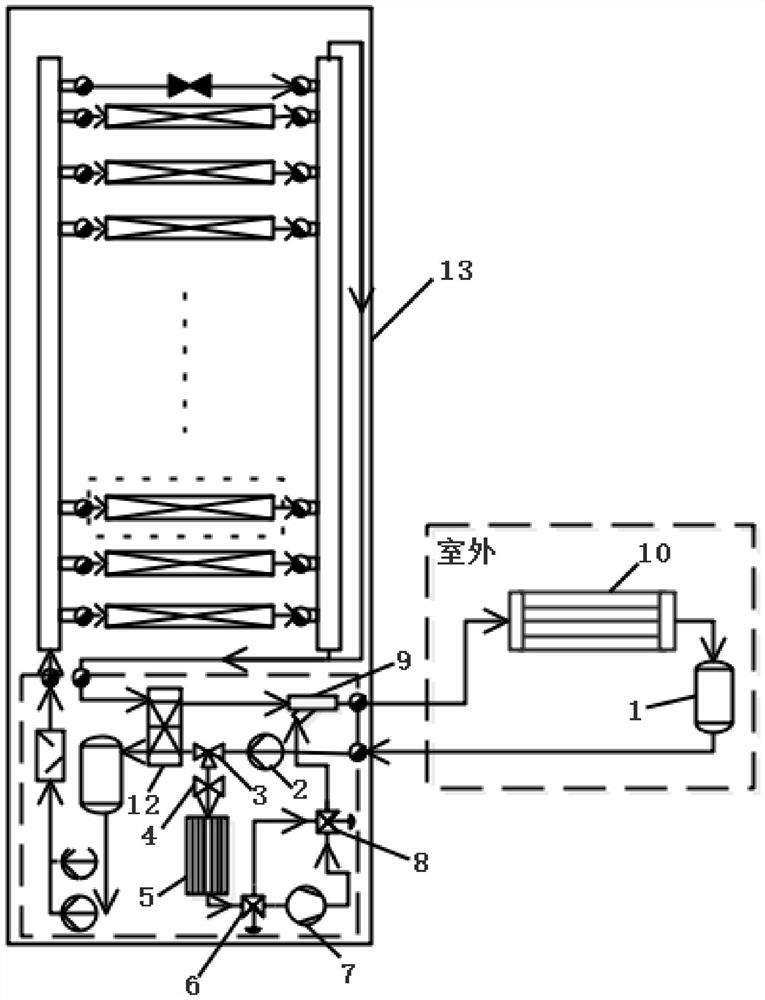
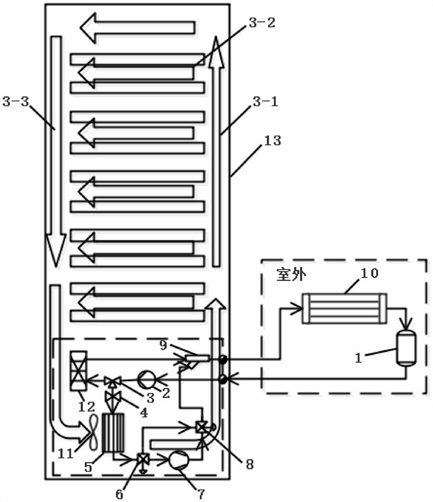
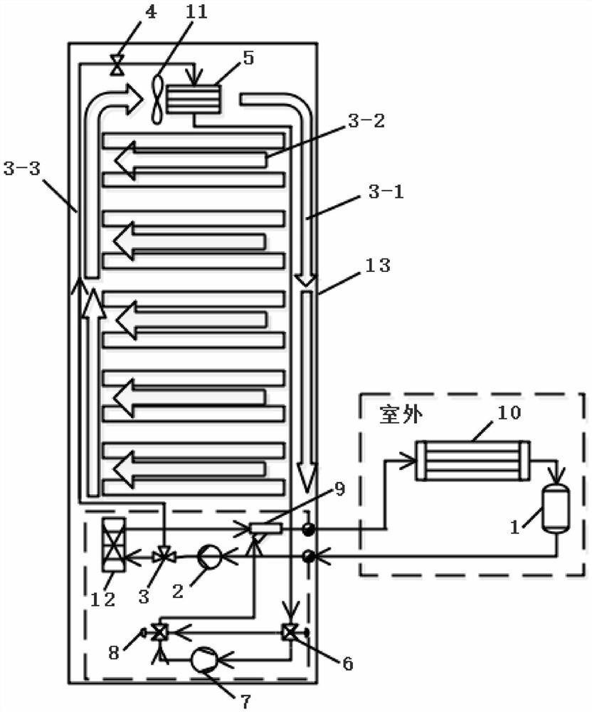
[0042] like Figure 1 to Figure 4 As shown, the overall high-efficiency heat dissipation system of the high power density cabinet according to the present invention is improved on the basis of the pump-driven two-phase loop high-power chip heat dissipation system, and its overall structure includes the pump-driven two-phase loop high-power chip heat dissipation system. System and cabinet air cooling system.

[0043] like figure 1 , figure 2 , image 3As shown, the cabinet air cooling system of the overall high-efficiency heat dissipation system for high power density cabinets according to the present invention includes a refrigerant circulation circuit and an air circulation circuit. In order to cope with different cycle conditions, the refrigerant cycle is divided into two circuits:

[0044] One road is a pump-driven two-phase circulation circuit, including refri...


PUM


Abstract

The invention discloses an overall efficient heat dissipation system of a high-power-density cabinet. The overall efficient heat dissipation system of the high-power-density cabinet comprises a pump-driven two-phase loop high-power chip direct heat dissipation system and a cabinet air cooling system. The cabinet air cooling system comprises a refrigerant circulation loop and an in-cabinet air circulation loop. In order to cope with different circulation working conditions, the refrigerant circulation loop can be divided into two paths, one path is a pump-driven two-phase circulation loop, andthe other path is a steam compression circulation loop. The pump-driven two-phase loop high-power chip direct heat dissipation system can carry out fixed-point heat dissipation on main heating elements such as a CPU and a GPU in a server, and the cabinet air cooling system can carry out air cooling heat dissipation on other heating elements of the server. Fixed-point heat dissipation of the high-power-density chip and air cooling heat dissipation of the low-power-density component are combined, on one hand, fixed-point heat dissipation can be directly conducted on the high-power chip, on the other hand, dependence of the server cabinet on air conditioner cooling can be avoided, and the problem of overall heat dissipation of the server cabinet is efficiently solved.

Description

technical field [0001] The invention relates to an overall high-efficiency cooling system for a cabinet with high power density. Background technique [0002] With the rapid development of information technology, the demand for servers with faster computing speed and more powerful functions has soared, which has led to a significant increase in the power density of a single cabinet. The main heating elements on the motherboard are CPU, GPU, etc., whose heating power accounts for 60% to 70% of the total heating power, and other heating elements on the motherboard account for 30% to 40% of the total heating power. Through the pump-driven two-phase loop high-power chip heat dissipation system, the heat dissipation of the main heating elements on the motherboard has been well solved, but the heat dissipation of other heating elements on the motherboard still needs to be solved. [0003] At present, when evaluating the energy efficiency of data centers, the PUE (Power Usage Effe...

Claims


Application Information

Patent Timeline
IPC IPC(8): H05K7/20
CPCH05K7/20754H05K7/20809H05K7/20818
Inventor 袁卫星杨通智任柯先苗泽杨波
Owner BEIHANG UNIV
Why Eureka
Try Eureka