Calibration device at tail end of orthopedic surgery robot

An orthopaedic surgery and calibration device technology, applied in surgical robots, surgical manipulators, etc., can solve the problems of complicated and complicated installation, delayed operation timing, waste of operation preparation time, etc., and achieve the effect of fast installation and good stability

Active Publication Date: 2020-09-08
HANGZHOU JOINTECH LTD
View PDF10 Cites 5 Cited by
  • Summary
  • Abstract
  • Description
  • Claims
  • Application Information

AI Technical Summary

Problems solved by technology

[0003] The installation between the traditional calibration reflective ball component and the calibration reflective ball base component is cumbersome and complicated, which wastes the preparation time for surgery and delays the best timing of surgery

Method used


Image

  • Calibration device at tail end of orthopedic surgery robot
  • Calibration device at tail end of orthopedic surgery robot
  • Calibration device at tail end of orthopedic surgery robot

Examples


Embodiment 1

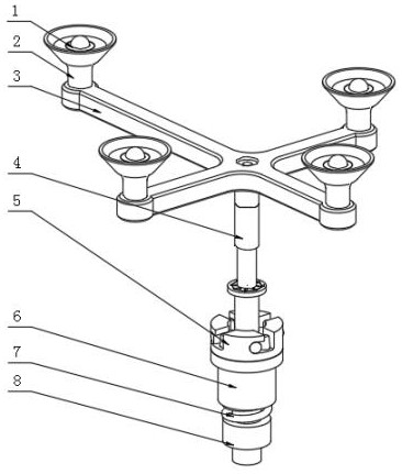
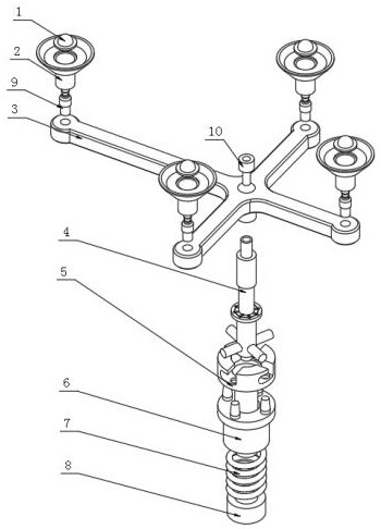
[0035] see Figure 1-2 , the present invention provides a technical solution: a calibration device for the end of an orthopedic surgical robot, including a calibration matrix base 3, a convex cylinder is fixedly installed on the lower side of the middle intersecting section of the calibration reflective ball member 1, and the middle intersection of the calibration matrix base 3 The section is provided with a countersunk threaded through hole, and the countersunk threaded through hole of the calibration matrix base 3 is provided with fastening screws 10, and the four ports of the calibration matrix base 3 are connected with four fixed support columns of the calibration matrix base 9. The four ports of the calibration matrix base 3 are fixed and supported by the four calibration matrix bases. The support column 9 is equipped with a calibration reflective ball base component 2, and a calibration reflective ball component 1 is arranged above the four calibration reflective ball bas...

Embodiment 2

[0041] see Figure 1-2 , the present invention provides a technical solution: a calibration device for the end of an orthopedic surgical robot, including a calibration matrix base 3, a convex cylinder is fixedly installed on the lower side of the middle intersecting section of the calibration reflective ball member 1, and the middle intersection of the calibration matrix base 3 The section is provided with a countersunk threaded through hole, and the countersunk threaded through hole of the calibration matrix base 3 is provided with fastening screws 10, and the four ports of the calibration matrix base 3 are connected with four fixed support columns of the calibration matrix base 9. The four ports of the calibration matrix base 3 are fixed and supported by the four calibration matrix bases. The support column 9 is equipped with a calibration reflective ball base component 2, and a calibration reflective ball component 1 is arranged above the four calibration reflective ball bas...


PUM


Abstract

The invention discloses a calibration device at tail end of an orthopedic surgery robot, and relates to the technical field of orthopaedic medical instruments. A calibration reflective ball base component comprises a calibration reflective ball base main body, the interior of the calibration reflective ball base main body is provided with a calibration reflective ball base sphere limiting groove located in the circle center of a calibration reflective ball base upper sinking groove, the interior of the calibration reflective ball base main body is provided with a calibration reflective ball base quick-mounting hemisphere part located at the bottom of the circle center of the calibration reflective ball base sphere limiting groove, the maximum diameter of the calibration reflective ball base fast-mounting hemisphere part is smaller than the diameter of the calibration reflective ball base sphere limiting groove, and a calibration reflective ball base fixing block is installed at the bottom of the calibration reflective ball base body. Existing calibration devices only need to perform calibration once, so that interference caused by matrix fixation in the operation process of an operator can be avoided, and the time of the whole operation can be fully saved.

Description

technical field [0001] The invention relates to the technical field of orthopedic medical devices, in particular to an orthopedic surgical robot terminal calibration device. Background technique [0002] Orthopedic devices generally refer to professional medical devices specially used for orthopedic surgery. According to the classification of the State Food and Drug Administration, it is often divided into: Class I; Class II and Class III. According to the use and performance, it is mainly divided into orthopedic knives, orthopedic scissors, orthopedic forceps, orthopedic hooks, orthopedic needles, orthopedic scrapers, orthopedic cones, orthopedic drills, orthopedic saws, orthopedic chisels, orthopedic. File / shovel, active instruments for orthopedics, etc. [0003] The installation between the traditional calibration reflective ball component and the calibration reflective ball base component is cumbersome and complicated, which wastes the preparation time for surgery and ...

Claims


Application Information

Patent Timeline
Patent Type & Authority Applications(China)
IPC IPC(8): A61B34/30
CPCA61B34/77A61B34/30
Inventor 荣健杜思傲许靖乔天宋亦旭董旭亮文理为王健
Owner HANGZHOU JOINTECH LTD
Why Eureka
Try Eureka