
Slurry supply pipe repair device and repair process thereof

A technology for feeding and repairing parts, applied in the field of repairing device for pulp supply pipe and its repairing process, can solve the problems of damage of internal rubber lining, reduction of production efficiency, outflow of slurry, etc., so as to increase service life, reduce outflow of slurry, and ensure smoothness Qi effect

Active Publication Date: 2020-09-08
杭州临江环保热电有限公司
View PDF11 Cites 0 Cited by
  • Summary
  • Abstract
  • Description
  • Claims
  • Application Information

AI Technical Summary

Problems solved by technology

[0004] The above-mentioned existing technical solutions have the following defects: due to the forming problem of the rubber lining in the above-mentioned slurry supply pipe during the manufacturing process, weak points are prone to appear at the connection between the rubber-lined pipe and the flange, and the weak points are enlarged under the scouring of the slurry, which gradually leads to The internal rubber lining is damaged, and the external pipeline is corroded and perforated
Moreover, since the rubber lining is inside the pipe and the outer pipe wall is thin, repair welding cannot be performed. Once the pipeline leaks slurry, the rubber lining pipe can only be replaced; during the replacement process, if the slurry supply is stopped, it will affect the continuity of production and reduce Production efficiency; if the slurry supply continues, the slurry will flow out, which will affect the environmental protection

Method used


Image

  • Slurry supply pipe repair device and repair process thereof
  • Slurry supply pipe repair device and repair process thereof
  • Slurry supply pipe repair device and repair process thereof

Examples


Embodiment 1

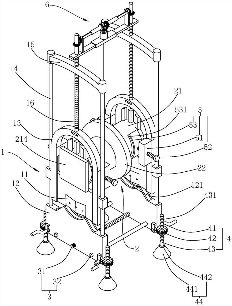
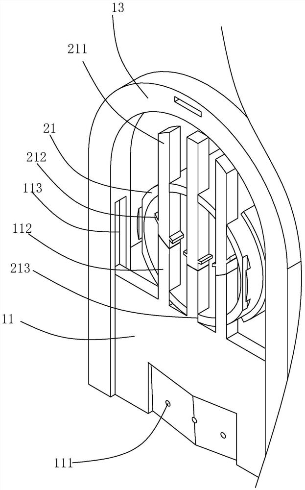
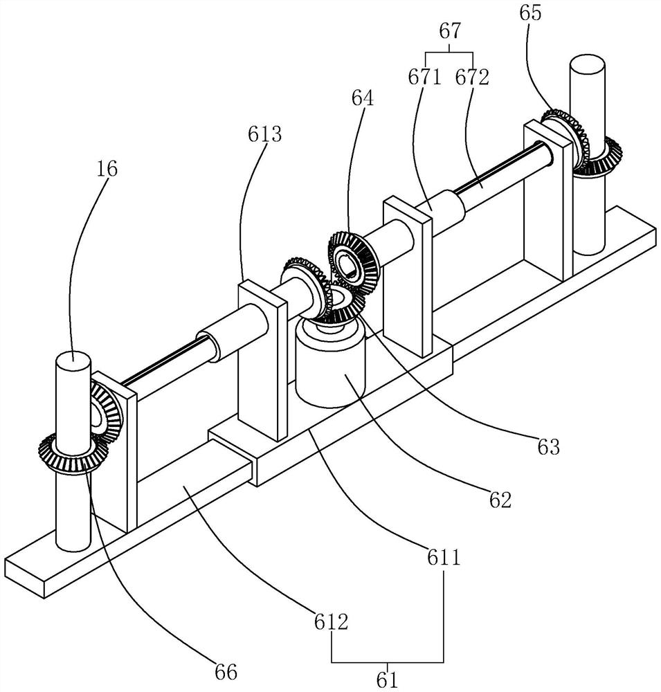
[0047] refer to figure 1 , is a slurry supply pipe repairing device disclosed in the present invention, comprising a cutting mechanism 1 for cutting a slurry leakage pipeline. The cutting mechanism 1 includes two sets of identical cutting parts respectively placed at both ends of the slurry leakage pipeline. Each set of cutting parts includes a base 12 , two guide rods 14 , a top frame 15 , a cutting frame 13 , a cutting knife 11 and a driving rod 16 .

[0048] refer to figure 1 , the top surface and the bottom surface of the base 12 of the two groups of cutting parts are all on the same horizontal plane, and the bottom surface of the base 12 is a horizontal plane. The top surface of each base 12 is provided with a cutting groove 121 , and the cutting groove 121 extends along the length direction of the top surface of the base 12 . Both ends of the cutting groove 121 protrude vertically upwards, and the middle part of the cutting groove 121 is recessed, so that the cutting g...

Embodiment 2

[0071] On the basis of Example 1, the present invention discloses a repair process for a slurry supply pipe repair device, comprising the following steps:

[0072] S1. Incision: through the downward pressure of two cutting knives, the two ends of the leakage pipeline are respectively cut into openings;

[0073] S2. Drainage: After the cutting knife cuts the opening, a part of the cutting knife will be placed in the pipeline. At this time, the slurry in the original pipeline and the leakage pipeline will flow to the stainless steel docked with the cutting knife under the drainage effect of the guide groove. tube;

[0074] S3, full cutting: through the continuous downward pressure of the two cutting knives, the two ends of the leakage pipeline are completely cut;

[0075] S4. Alignment: the stainless steel pipe moves down with the cutting knife until the two ends of the stainless steel pipe are aligned with the ports of the original pipe and fit neatly;

[0076] S5. Welding: b...


PUM


Abstract

The invention relates to a slurry supply pipe repair device and a repair process, and relates to the technical field of slurry supply pipes. The slurry supply pipe repair device comprises a cutting mechanism used for cutting a pipeline and a repair piece which is mounted on the cutting mechanism; the cutting mechanism comprises cutters; the top surfaces of the cutters are fixedly connected with material guide blocks; a communicating material guide groove is formed in each cutter and the corresponding material guide block in common; the orientations of the ports in the two ends of the materialguide groove are opposite; a groove opening in the upper end of each material guide groove is formed in the side wall of the corresponding material guide block; a groove opening in the lower end of each material guide groove is formed in one surface, facing a cut pipeline, of the corresponding cutter; the repair piece comprises a stainless steel flange piece and stainless steel pipes which are respectively butt-welded at the ports of the stainless steel flange piece; notches, which are adapted to the material guide blocks, are formed in the bottom surface, far away from one end of the stainless steel flange piece, of the stainless steel pipes; and the stainless steel pipes are butted with the cutters through the notches. The slurry supply pipe repair device and the repair process have theeffects of replacing the overall section of a slurry leaking position while supplying slurry.

Description

technical field [0001] The invention relates to the technical field of a slurry supply pipe, in particular to a repair device for a slurry supply pipe and a repair process thereof. Background technique [0002] The wet desulfurization device is located at the end of the flue and after the dust collector. Due to the gas-liquid reaction, the desulfurization reaction speed is fast, the efficiency is high, and the utilization rate of the desulfurization additive is high: if lime is used as the desulfurizer, when Ca / S=1 , can achieve a desulfurization rate of 70%, suitable for flue gas desulfurization of large coal-fired power plants. The limestone slurry tank is used to supply slurry for the desulfurization absorption tower. The slurry supply pipe used in the slurry supply is composed of inner rubber and outer 20#, which mainly plays the role of wear resistance and anticorrosion. [0003] For the existing technology, please refer to the utility model patent with the authorized ...

Claims


Application Information

Patent Timeline
Patent Type & Authority Applications(China)
IPC IPC(8): B23P6/00
CPCB23P6/00
Inventor 丁晨金飞刘慧鹏鲍军荣戴林祥马阳初
Owner 杭州临江环保热电有限公司
Learn More