Printing and dyeing device for textile with automatic feeding structure

A printing and dyeing equipment and automatic feeding technology, which is applied in the field of printing and dyeing, can solve the problems of time-consuming and laborious, the non-dense winding of textile fabrics, and the inability to adjust the tension of textile fabrics, etc., and achieve a good drying effect

Pending Publication Date: 2020-09-08
嘉兴程熙纺织品有限公司
View PDF0 Cites 3 Cited by
  • Summary
  • Abstract
  • Description
  • Claims
  • Application Information

AI Technical Summary

Problems solved by technology

As the printing and dyeing processing technology becomes more and more mature, people have invented printing and dyeing equipment to print and dye textile fabrics. When the existing printing and dyeing equipment is in use, it is necessary to manually observe the storage capacity of the dye regularly. When the dye is insufficient, it needs to be added manually, which is time-consuming and laborious. , and the dust and impurities on the surface of the textile fabric cannot be cleaned, which will affect the printing and dyeing effect. After printing and dyeing, it is necessary to wait for the dye to dry before the textile fabric can be rolled up. The waiting time is long, and the tension of the textile fabric cannot be adjusted so that the textile fabric The cloth is not rolled tightly, so we propose a textile printing and dyeing equipment with automatic feeding structure to solve this problem

Method used


Image

  • Printing and dyeing device for textile with automatic feeding structure
  • Printing and dyeing device for textile with automatic feeding structure
  • Printing and dyeing device for textile with automatic feeding structure

Examples


Embodiment Construction

[0026] The following will clearly and completely describe the technical solutions in the embodiments of the present invention with reference to the accompanying drawings in the embodiments of the present invention. Obviously, the described embodiments are only some, not all, embodiments of the present invention.

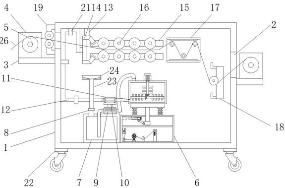
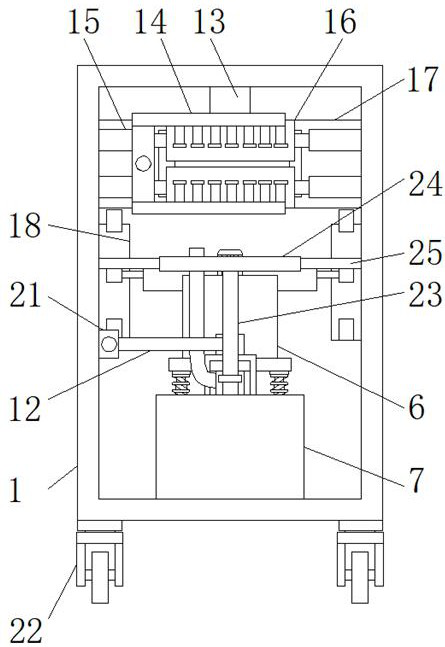
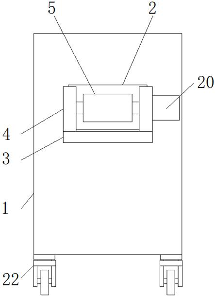
[0027] refer to Figure 1-9 , a printing and dyeing equipment with an automatic feeding structure for textiles, including a box body 1, universal wheels 22 are fixedly installed at the four corners of the bottom of the box body 1, and the printing and dyeing equipment can be moved according to needs through the universal wheels 22. Ease of use.

[0028] Both the left upper part and the right upper part of the box body 1 are provided with an opening 2, and the left and right sides of the box body 1 and directly below the opening 2 are fixedly installed with a carrier plate 3, and the front and rear sides of the top of the carrier plate 3 are fixed. A baffle 4 is inst...


PUM


Abstract

The invention relates to the technical field of printing and dyeing, in particular to a printing and dyeing device for textile with an automatic feeding structure. The printing and dyeing device comprises a box body. The upper portion of the left side and the upper portion of the right side of the box body are each provided with an opening. The positions, located under the openings, of the left side and the right side of the box body are each fixedly provided with a carrier plate. The front side and the rear side of the top end of each carrier plate are each fixedly provided with a baffle. Dyes can be automatically supplemented in the printing and dyeing process, the dye amount is kept at a constant value, there is no need to manually observe the dye storage amount and supplement the dyesregularly, dust and impurities can be removed from textile fabrics before printing and dyeing, the printed and dyed textile fabrics can be dried through a drying device, the printing and dyeing devicehas a tension degree adjusting function and a dye recovery function, it is avoided that sprayed dyes drip to be wasted, the dyes can be stirred to be prevented from uneven composition distribution, and the printing and dyeing device can be conveniently moved according to needs and is worthy of popularization and use.

Description

technical field [0001] The invention relates to the technical field of printing and dyeing, in particular to a textile printing and dyeing device with an automatic feeding structure. Background technique [0002] Printing and dyeing, also known as dyeing and finishing, is a processing method and a general term for pretreatment, dyeing, printing, finishing, washing, etc.; the undergraduate dyeing and finishing major has now been merged into the light chemical engineering major; Thousands of years ago in the Neolithic Age, our ancestors were able to dye linen red with hematite powder. As the printing and dyeing processing technology becomes more and more mature, people have invented printing and dyeing equipment to print and dye textile fabrics. When the existing printing and dyeing equipment is in use, it is necessary to manually observe the storage capacity of the dye regularly. When the dye is insufficient, it needs to be added manually, which is time-consuming and laboriou...

Claims


Application Information

Patent Timeline
IPC IPC(8): D06B1/02D06B23/20D06B15/00D06G1/00B65H20/02B65H23/188
CPCB65H20/02B65H23/1888B65H2701/1133D06B1/02D06B15/00D06B23/20D06G1/00
Inventor 员贤荣陈佳淇
Owner 嘉兴程熙纺织品有限公司
Why Eureka
Try Eureka