Device and method for testing compression performance of granular filling under dynamic-static acting force

A testing device and force technology, applied in the direction of applying stable tension/pressure to test material strength, measuring device, strength characteristics, etc., can solve the problems of not considering the influence of dynamic load compression characteristics, single function, etc., to maintain air The effect of stable area, simple operation, and inhibition of deformation and damage

Active Publication Date: 2020-09-08
NORTHEASTERN UNIV
View PDF13 Cites 6 Cited by
  • Summary
  • Abstract
  • Description
  • Claims
  • Application Information

AI Technical Summary

Problems solved by technology

[0003] Chinese patent application CN203053782U made a self-made test compression mold for coal gangue, which mainly performs static compression tests on loose gangue. Its function is relatively single, and the influence of dynamic load on compression characteristics is not considered.

Method used


Image

  • Device and method for testing compression performance of granular filling under dynamic-static acting force
  • Device and method for testing compression performance of granular filling under dynamic-static acting force

Examples


Embodiment 1

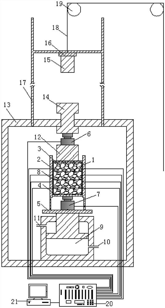
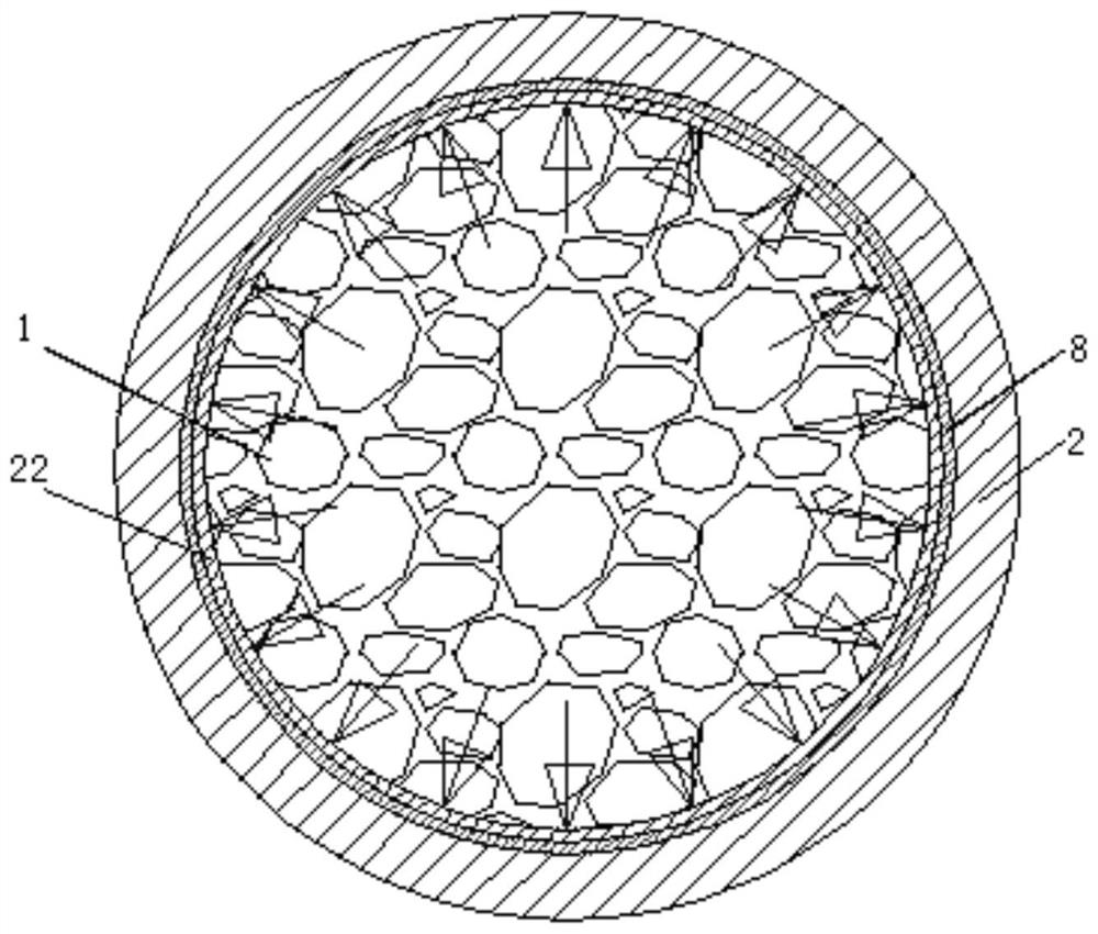
[0041] like figure 1 and figure 2 As shown, the test device for the compression performance of the filling powder under dynamic-static force includes a hydraulic cylinder 9, a steel structure frame 13, a lifting platform 5, and a loading plug 12; the bottom end of the steel structure steel frame is arranged on the ground A hydraulic cylinder 9 is installed on the upper surface of the bottom end of the steel structure frame 13, and the loading and unloading of the test bulk 1 is realized through the pressurized oil inlet 10 and the pressure relief oil inlet 11 of the hydraulic cylinder 9, and the piston rod of the hydraulic cylinder 9 extends The end of the cylinder part is provided with a lifting platform 5, and the upper surface of the lifting platform 5 is provided with a cylindrical device 2 and a first load sensor 7, and the first load sensor 7 is located in the inner cavity of the cylindrical device 2, and the cylindrical device 2 is connected to the The input end of th...

Embodiment 2

[0055] The difference between embodiment 2 and embodiment 1 is that embodiment 2 is a dynamic impact test.

[0056] The test method for the compression performance of filling bulk under dynamic impact force includes the following steps:

[0057] Considering the influence of dynamic impact force on the compression performance of test bulk 1, the influence of different magnitudes of dynamic impact force on the compression performance of test bulk 1 under different bearing pressures was studied.

[0058] Step 1. Put the hydraulic cylinder 9 into the bottom of the steel structure frame 13, place the cylinder on the lifting platform 5 of the hydraulic cylinder 9, and ensure that the cylinder is aligned with the axial centerline of the lifting platform 5; place the first load sensor 7 and the bottom plate 4 are put into the cylinder in turn, and the bottom plate 4 is installed above the first load sensor 7, and the bottom plate 4 is adjusted to be horizontal by observing the four eq...


PUM

PropertyMeasurementUnit
angleaaaaaaaaaa
thicknessaaaaaaaaaa

Abstract

The invention discloses a device and a method for testing compression performance of granular filling under dynamic-static acting force. The device comprises a hydraulic cylinder and a steel structureframe. The hydraulic cylinder is mounted in the upper surface of the bottom end of the steel structure frame. A lifting platform, a cylinder device, a first load sensor, a loading plunger and a second load sensor are sequentially arranged at the top of the hydraulic cylinder; a movable loading H-shaped block, a support, an impact iron block and an electromagnet are sequentially arranged at the top of the steel structure frame, the electromagnet is connected with a steel rope, the cylinder device is connected with a computer through a wire and a multi-channel static strain gauge, and the second load sensor and the first load sensor are connected with the multi-channel static strain gauge through wires. According to the device and method, the compression amount and modulus characteristics of waste rock particles under the static action can be obtained, the lateral pressure of the particles under pressure can be measured, the lateral pressure is beneficial to restraining deformation anddamage of pillar surrounding rock, the strength of pillars and surrounding rock is improved, the goaf stability is maintained, and the lateral pressure distribution in the filling particles plays an important guiding role in filling mining design.

Description

technical field [0001] The invention belongs to the technical field of ore deposit filling and mining, and in particular relates to a testing device and method for the compression performance of filling bulk under dynamic-static force. Background technique [0002] With the rapid development of the national economy, the demand for mineral resources is increasing year by year. The mining of "three lower" (under the village, under the water body and under the railway) ore bodies and deep metal mineral resources has become an important research in the field of mineral resource mining. As an effective way to liberate the "three lower" ore bodies, the solid waste filling mining technology such as waste rock and tailings can not only effectively control the movement of the overlying strata in the stope, limit the surface subsidence, but also effectively control the movement of the overlying strata in the stope, and in the special environment of deep mining. Under such circumstance...

Claims


Application Information

Patent Timeline
Patent Type & Authority Applications(China)
IPC IPC(8): G01N3/12G01N3/303G01N3/02G01N3/06
CPCG01N3/02G01N3/06G01N3/12G01N3/303G01N2203/0003G01N2203/001G01N2203/0033G01N2203/0048
Inventor 于庆磊勒治华朱万成杨天鸿牛雷雷曹永胜
Owner NORTHEASTERN UNIV
Why Eureka
Try Eureka