Automobile millimeter wave radar waveform design method for efficient speed ambiguity resolution

A technology of millimeter-wave radar and radar waveform, which is applied in the direction of utilizing re-radiation, radio wave measurement system, radio wave reflection/re-radiation, etc., which can solve the problem that the millimeter-wave radar system has a large demand for RAM capacity and it is difficult to shorten the millimeter-wave radar system. Problems such as system update cycle and large RAM space can achieve the effect of shortening the launch time, reducing the risk of occurrence, and reducing the storage capacity

Active Publication Date: 2020-09-08
HUAYU AUTOMOTIVE SYST
View PDF4 Cites 3 Cited by
  • Summary
  • Abstract
  • Description
  • Claims
  • Application Information

AI Technical Summary

Problems solved by technology

However, this waveform design takes up a lot of RAM space in the entire vehicle auxiliary system, and the radar target velocity update method of the traditional millimeter-wave radar needs to store and process data in each system cycle due to its waveform design and the need for velocity deambiguation The amount will increase rapidly with the improvement of the speed resolution and other indicators, which will cause a large demand for the RAM capacity of the entire millimeter-wave radar system; at the same time, due to the long cycle and high difficulty of optimization, it is difficult to shorten the entire millimeter-wave radar system. System update cycle, so it is difficult to meet the increasingly urgent needs of OEMs and other customers for shortening the update and alarm cycle of millimeter wave radar sensors, and it is difficult to reduce the entire system cycle to less than 40ms

Method used


Image

  • Automobile millimeter wave radar waveform design method for efficient speed ambiguity resolution
  • Automobile millimeter wave radar waveform design method for efficient speed ambiguity resolution
  • Automobile millimeter wave radar waveform design method for efficient speed ambiguity resolution

Examples


Embodiment Construction

[0039] Below in conjunction with the drawings, preferred embodiments of the present invention are given and described in detail.

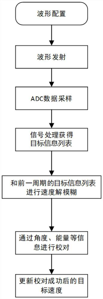
[0040] like image 3 Shown is an automotive millimeter-wave radar waveform design method for efficient velocity deambiguation according to an embodiment of the present invention, which is used in a radar system, especially a millimeter-wave radar system. The technical idea of ​​the automotive millimeter-wave radar waveform design method for high-efficiency velocity deambiguation of the present invention is: separate the first waveform and the second waveform that were originally transmitted in one system cycle, and sequentially generate Transmit the first waveform and the second waveform in sequence, and then perform speed defuzzification on the target information obtained after signal processing of the current system cycle and the previous cycle, and obtain the actual speed information of the target, which can be carried out through information su...


PUM


Abstract

The invention provides an automobile millimeter wave radar waveform design method for efficient speed ambiguity resolution. The method comprises the steps: setting a system period, and setting the parameters of various radar waveforms; alternately transmitting signals of the various radar waveforms to a radar target in a plurality of continuous system periods, and only transmitting signals of oneradar waveform in each system period; in each system period, carrying out ADC sampling on the radar waveforms; carrying out signal processing on the the radar waveforms to obtain information lists ofthe current radar targets, and recording the information lists into a memory; performing speed ambiguity resolution according to the information lists of the radar targets in the current and previousN system periods, wherein N is less than or equal to M-1; checking the target information; updating the speed information of the radar targets passing proofreading operation. According to the radar waveform design method, only one waveform is transmitted in each system period, so that the transmitting time of the system waveforms is effectively shortened, and the updating period of the whole radarsystem is shortened; required storage capacity is reduced, and risk of ambiguity resolution errors is reduced.

Description

technical field [0001] The invention belongs to the field of automotive millimeter-wave radar design, and in particular relates to an automotive millimeter-wave radar waveform design method for high-efficiency velocity defuzzification. Background technique [0002] With the vigorous development of the current autonomous driving industry, millimeter-wave radar sensors are an important component of automotive intelligent driving assistance systems, and people have higher and higher performance requirements for them. Generally speaking, automotive radar systems need to accurately measure the distance, velocity and angle of target objects in real time, and even in the case of multiple targets, they need to be able to accurately distinguish and track these targets through velocity deblurring. In order to realize this requirement, the waveform design of the millimeter-wave radar sensor is a very important part of the radar system design. However, under the traditional millimeter-...

Claims


Application Information

Patent Timeline
Patent Type & Authority Applications(China)
IPC IPC(8): G01S13/66G01S13/58G01S7/41
CPCG01S13/66G01S13/58G01S7/418
Inventor 房旭龙厉瀚杰王阶孙双锁
Owner HUAYU AUTOMOTIVE SYST
Why Eureka
Try Eureka