
Communication navigation identification system module test platform

A module testing and identification system technology, applied in transmission systems, electrical components, etc., can solve problems such as high data error rate, low efficiency, and inability to truly restore the airborne bus communication environment

Pending Publication Date: 2022-01-21
10TH RES INST OF CETC
View PDF7 Cites 2 Cited by
  • Summary
  • Abstract
  • Description
  • Claims
  • Application Information

AI Technical Summary

Problems solved by technology

In the process of module testing using a traditional test system, the binary data stream of the airborne interface is manually input by the tester, and the index data on the test equipment is also watched and monitored by the tester himself. The test record also requires a lot of manual input and export operations. There are some problems and defects in these methods: 1. When the interface design is iteratively updated, the interface binary data stream is manually input, which is highly error-prone and has a high data error rate; 2. Relying on manual operation testing, the bus data during the test process The timeliness of communication is difficult to meet, and it is impossible to truly restore the airborne bus communication environment; 3. Relying on manual observation and recording, the efficiency is low, and the test coverage rate is not easy to quantify. Objectively, there may be missed tests, and the test coverage rate is low; 4. During the module performance test, the previous module function and performance optimization schemes and experience were not well preserved and inherited, mainly relying on the accumulation of personal test experience, which prolongs the improvement cycle of the module that meets the module performance requirements

Method used


Image

  • Communication navigation identification system module test platform
  • Communication navigation identification system module test platform
  • Communication navigation identification system module test platform

Examples


Embodiment Construction

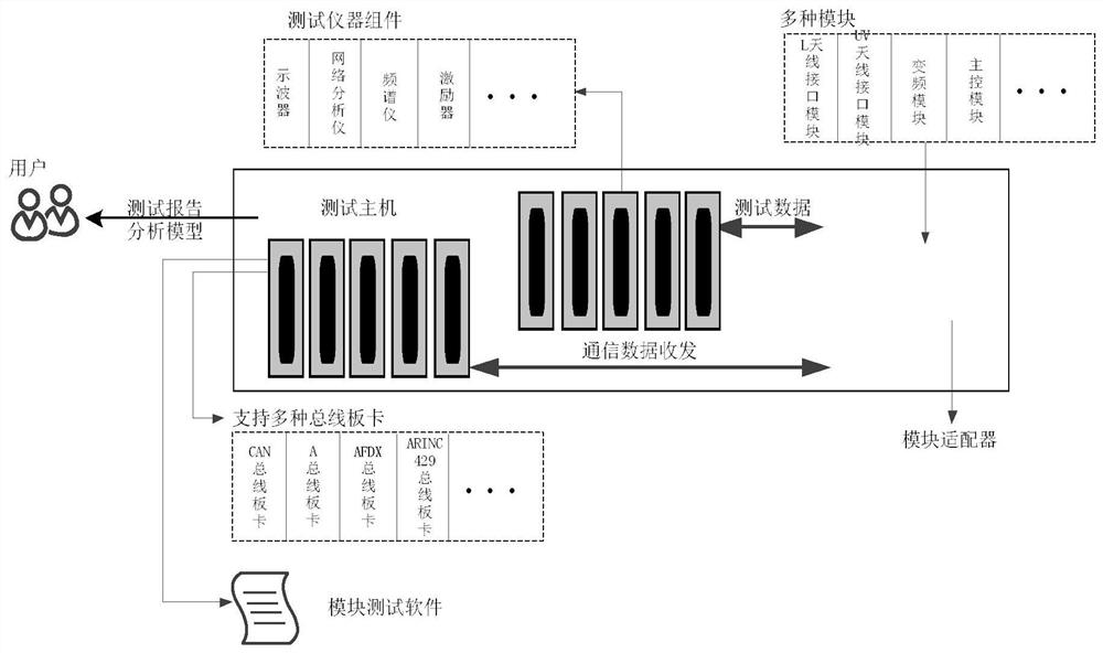
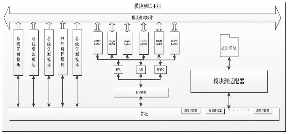
[0020] refer to figure 1 . In the exemplary preferred embodiment described below, a communication navigation identification system module test platform includes: a test host that is provided with bus modularization, test instrument componentization, and contains module test software and performs two-way communication with the test host The module adapter, the module adapter resides on the test mainframe chassis through a connector. Among them: the test host aims at high integration and compatibility, including a variety of bus IO resources, combined with vector network analyzer (VSA), RF vector signal analyzer, baseband vector signal analyzer vector and signal generator (VSG) , Based on the real-time signal processing and control of programmable FPGA, the general test instrument is integrated into one or more modules, as well as high-speed serial and parallel digital interfaces, and the general test instrument is modularized and componentized, and integrated into the test hos...


PUM


Abstract

The communication navigation identification system module test platform disclosed by the invention is high in execution efficiency, easy in case editing operation and extensible in software and hardware. According to the technical scheme, a test host carries out real-time signal processing and control based on an FPGA, general test instrument equipment is modularly integrated into a test host box body, scheduling of test tasks is organized and managed according to excitation signals provided by an excitation unit, and the test efficiency is improved. On-line debugging and signal detection are monitored in real time by receiving and transmitting communication data, adaptive switching of a switch matrix, automatic acquisition and recording of performance index test data of a tested module and synchronous control are realized, a communication environment of data interaction of various types of buses of the tested module in an airborne system is simulated, and automatic test of performance is realized; by collecting test data of the test instrument assembly, a test report analysis model and a test result data management center are established, a test report is automatically generated, and different test resources and test conclusions are output.

Description

technical field [0001] The invention relates to the field of test and measurement, and is a module test platform mainly used in an avionics communication navigation identification system (CNI). Background technique [0002] With the rapid development of avionics and computer technology, the degree of integration of avionics systems is increasing day by day, and higher requirements are put forward for system testing. Among them, the research of communication navigation identification system is very important. However, there are currently a series of problems in the airborne communication, navigation, and identification functions. As an important part of the aircraft avionics system, the communication navigation identification system is particularly important for the integrity test of the module function and the quality test of the performance index. But in the airborne equipment test, the test of communication navigation identification equipment is the most complicated. In...

Claims


Application Information

Patent Timeline
IPC IPC(8): H04L43/50
CPCH04L43/50
Inventor 张钰婧陈赟王东雷婉琦杜增王立
Owner 10TH RES INST OF CETC
Learn More