Eureka AIR delivers breakthrough ideas for toughest innovation challenges, trusted by R&D personnel around the world.

Passenger flow confluence walking behavior simulation method for station facility combination part

A joint and facility technology, applied in design optimization/simulation, special data processing applications, instruments, etc., can solve problems such as few setting scenes, lack of influence of passenger flow mechanism, and less attention to facility joints.

Pending Publication Date: 2020-09-08
BEIJING JIAOTONG UNIV
View PDF4 Cites 0 Cited by
  • Summary
  • Abstract
  • Description
  • Claims
  • Application Information

AI Technical Summary

Problems solved by technology

[0009] (3) Research on the mechanism of passenger flow mostly relies on field experiments to explore the impact of passenger flow status on traffic efficiency, or the impact of changes in the geometric attributes of a single facility in a subway station on service levels, and less attention is paid to the junction of facilities. There is a lack of research on the influence of the geometric properties of facilities, the way of confluence and the coupling effect of channel structure on the mechanism of passenger flow.
[0010] (4) At present, when considering the influence of geometric characteristics such as aisle width and merging angle on the mechanism of passenger flow, there are few scenarios set up, and most of the conclusions obtained are qualitative conclusions
It is not yet clear whether there is a quantitative relationship between the geometric properties of the facility and the running parameters

Method used


Image

  • Passenger flow confluence walking behavior simulation method for station facility combination part
  • Passenger flow confluence walking behavior simulation method for station facility combination part
  • Passenger flow confluence walking behavior simulation method for station facility combination part

Examples


Embodiment Construction

[0104] The following describes the embodiments of the present invention in detail. Examples of the embodiments are shown in the accompanying drawings, wherein the same or similar reference numerals indicate the same or similar elements or elements with the same or similar functions. The following embodiments described with reference to the accompanying drawings are exemplary, and are only used to explain the present invention, and cannot be construed as limiting the present invention.

[0105] Those skilled in the art can understand that, unless specifically stated otherwise, the singular forms "a", "an", "said" and "the" used herein may also include plural forms. It should be further understood that the term "comprising" used in the specification of the present invention refers to the presence of the described features, integers, steps, operations, elements and / or components, but does not exclude the presence or addition of one or more other features, Integers, steps, operations...


PUM


Abstract

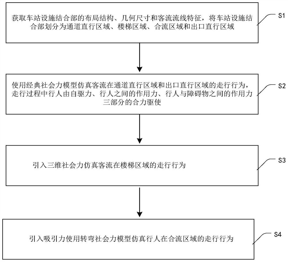
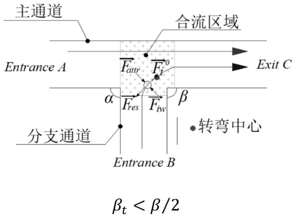
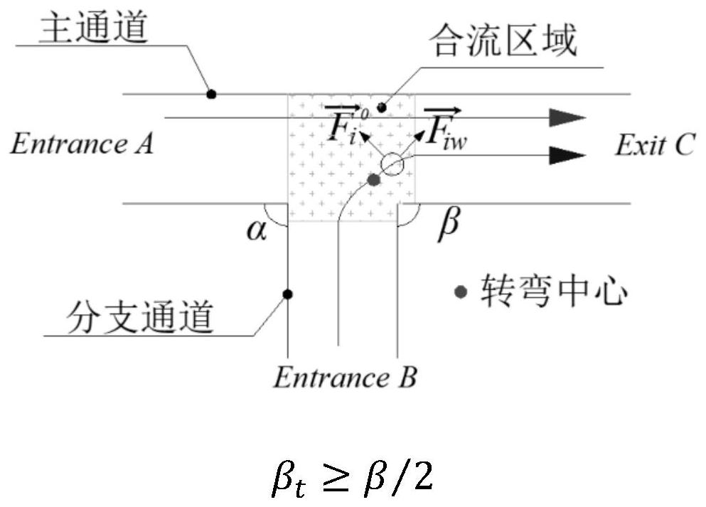
The invention provides a passenger flow confluence walking behavior simulation method for a station facility combination part. The method comprises the steps that the layout structure, the geometric dimension and the passenger flow streamline characteristics of a station facility combination part are obtained, and the station facility combination part is divided into a channel straight-going area,a stair area, a confluence area and an exit straight-going area; a classic social force model is used to simulate the walking behaviors of the passenger flow in the passage straight-going area and the exit straight-going area; a three-dimensional social force is introduced to simulate the walking behavior of the passenger flow in the stair area; attraction is introduced, and a turning social force model is used for simulating walking behaviors of pedestrians in a confluence area. According to the method, walking parameters under different scenes are simulated and quantified, the walking stateand the facility area passing rate are constructed to serve as indexes of bottleneck recognition through the relation between time and the layout structure and the geometrical attribute of a channel,and improvement suggestions are provided for confluence area passenger flow motion optimization and facility combination part design.

Description

Technical field [0001] The present invention relates to the technical field of urban rail transit, in particular to a method for simulating the combined walking behavior of passenger flow at the junction of station facilities. Background technique [0002] According to the statistics of Beijing subway operation data, the daily inbound passenger flow of busy stations exceeds 250,000, and congestion in the stations has become a normal operation. There are complex pedestrian flow lines in the facility junctions, which are prone to traffic jams and cause safety hazards in subway stations. To improve the efficiency and service level of passenger flow, it is necessary to deepen and refine the travel mechanism of passenger flow at the junction of facilities. Combination behavior is an important walking behavior at the junction of facilities, and it often occurs in areas where people moving in multiple directions form a single flow through turning and merging movements. The confluence ...

Claims


Application Information

Patent Timeline
IPC IPC(8): G06Q10/06G06F30/20G06Q50/26G06F119/14
CPCG06Q10/067G06F30/20G06Q50/26G06F2119/14
Inventor 徐杰梁梦迪张慧史艺菡贾利民秦勇陈益雯
Owner BEIJING JIAOTONG UNIV
Why Eureka
Eureka Blog
Learn More