Unlock instant, AI-driven research and patent intelligence for your innovation.

Floating guide mechanism

A guiding mechanism and lifting technology, which is applied in the field of stamping dies, can solve the problems of insufficient mold space and the inability to place floating guide devices, etc., and achieve the effects of simple and ingenious structure, space saving and strong practicability

Pending Publication Date: 2020-09-11
WUXI MINGHAO AUTOMOTIVE PARTS
View PDF0 Cites 0 Cited by
  • Summary
  • Abstract
  • Description
  • Claims
  • Application Information

AI Technical Summary

Problems solved by technology

[0003] The invention provides a floating guiding mechanism, which solves the problem that the floating material guiding device cannot be placed due to insufficient mold space in the prior art

Method used


Image

  • Floating guide mechanism
  • Floating guide mechanism

Examples


Embodiment Construction

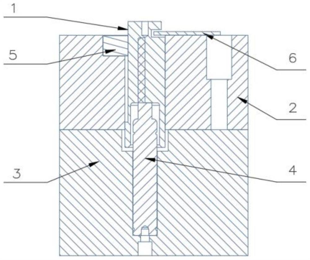
[0015] Such as figure 1 , figure 2 , the structure of the present invention is, including pin side guide post 1, guide post fixing plate 2, mold base 3, nitrogen spring 4,

[0016] The upper side of the pin edge guide post 1 has a limit pin edge on the peripheral surface of one side, and a guide bar 6 is installed horizontally outward in the limit pin edge, and the lower part of the pin edge guide post 1 is processed with a guide corrugated along the other side of the circumferential surface opposite in diameter. The lower end surface of the pin edge guide post 1 is provided with two-stage blind hole type nitrogen spring installation grooves;

[0017] A guide post installation groove is vertically opened in the guide post fixing plate 2, and the pin edge guide post 1 passes through the guide post installation groove. The upper edge of the guide post installation groove is provided with a stepped pressure plate installation groove, and the pressure plate installation groove ...


PUM


Abstract

The invention discloses a floating guide mechanism. A material guide strip is mounted in the middle of a limiting pin edge of the circumferential surface of one side of the upper portion of a pin edgeguide pillar, and a guide ridge is machined on the circumferential surface of the opposite other side along the diameter of the lower portion of the pin edge guide pillar; a guide pillar mounting groove is vertically formed in a guide pillar fixing plate, the pin edge guide pillar penetrates through the guide pillar mounting groove, a stepped pressing plate mounting groove is formed in the upperedge of the guide pillar mounting groove, and a pressing plate is mounted in the pressing plate mounting groove; a guide groove is formed in the guide pillar mounting groove and upwards rightly facesthe pressing plate, and a guide edge of the pin edge guide pillar is sleeved with the guide groove; and a nitrogen spring mounting hole and a countersunk head hole are vertically formed in a die holder, the nitrogen spring mounting hole and the countersunk head hole communicate up and down, a nitrogen spring is mounted in the nitrogen spring mounting hole, the nitrogen spring is upwards connectedwith the pin edge guide pillar in a pressing mode, and the guide pillar fixing plate is downwards and fixedly connected with the die holder by utilizing a countersunk head screw. According to the mechanism, the material guide strip can be guided while floating is realized.

Description

technical field [0001] The invention belongs to the technical field of stamping dies, and relates to a lifting guide mechanism. Background technique [0002] At present, floating material feeding is widely used in the actual application of continuous die production, because the continuity of floating material and feeding is very important in ensuring the continuous production of progressive dies. In the progressive die, the traditional lifting and guiding mechanism is a combination of guide pillars, springs and guide strips. The lift is guided by the guide pillars, the spring gives the buoyancy force, and the feeding is guided by the guide strips. However, when the guide pillars, springs and guide strips are arranged in a narrow space, the space will be relatively compact and crowded; in a place with a large space, if the spring is too far away from the guide pillars, the guide pillars will be tilted and stuck, and the buoyancy will be realized. Relatively troublesome. Co...

Claims


Application Information

Patent Timeline
IPC IPC(8): B21D37/12
CPCB21D37/12
Inventor 笪旭
Owner WUXI MINGHAO AUTOMOTIVE PARTS
Features
  • R&D
  • Intellectual Property
  • Life Sciences
  • Materials
  • Tech Scout
  • Unparalleled Data Quality
  • Higher Quality Content
  • 60% Fewer Hallucinations
Learn More