Circular tube cross-shaped welding auxiliary clamping method

A cross welding and clamping technology, applied in welding equipment, laser welding equipment, tubular objects, etc., can solve problems such as overall deformation of the cross shape, reduce energy consumption, ensure production speed, and be less susceptible to thermal deformation.

Inactive Publication Date: 2020-09-11
江苏统联科技股份有限公司
View PDF11 Cites 2 Cited by
  • Summary
  • Abstract
  • Description
  • Claims
  • Application Information

AI Technical Summary

Problems solved by technology

[0003] Aiming at the defects of the above-mentioned prior art, the present invention provides an auxiliary clamping method for round pipe cross welding, which solves the problem that the cross shape is deformed as a whole due to the deformation of the head of the short round pipe during welding.

Method used


Image

  • Circular tube cross-shaped welding auxiliary clamping method
  • Circular tube cross-shaped welding auxiliary clamping method
  • Circular tube cross-shaped welding auxiliary clamping method

Examples


Embodiment 1

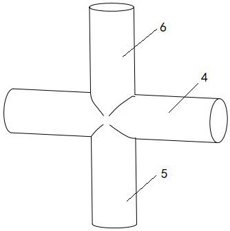
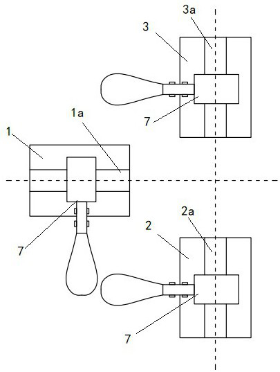
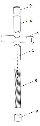
[0016] Embodiment 1. Please combine the auxiliary clamping method for cross welding of round tubes involved in this embodiment. image 3 As shown, the use of auxiliary tools including a screw 8 and a cylindrical nut 9, the screw 8 is used as a guide rod, on the screw 8, the first short tube 5 is axially threaded, the long tube 4 is traversed from the welding position, and the second is axially threaded. The short tube 6 makes the first short tube 5, the long tube 4 and the second short tube 6 form a cross-shaped structure. The cylindrical nut 9 is used as the top column, and the cylindrical nut 9 is screwed on the two ends of the screw 8 completed by the above-mentioned sleeve and tightened so that the first short tube 5 and the second short tube 6 are axially compressed to complete the assembly. Put the assembled cross-shaped structure into each positioning block for clamping as in the prior art, the upper and lower sides of the second slotted positioning block 2 and the thir...

Embodiment 2

[0017] Embodiment 2. Please combine the auxiliary clamping method for cross welding of round tubes involved in this embodiment. Figure 4 As shown, the use of auxiliary tools includes a guide rod 10 and a cylindrical nut 11 with a rod, the rod body of the guide rod 10 is a smooth round rod, the head of the guide rod 10 is provided with threads, and the tail end of the guide rod 10 is a section with a diameter larger than that of the guide rod 10. The cylindrical section of the rod body but not larger than the diameter of the first short tube 5 and the second short tube 6, on the guide rod 10, the first short tube 5 is axially sleeved in sequence, the long tube 4 is crossed by the welding position, and the axial penetration is Cover the second short tube 6 so that the first short tube 5 , the long tube 4 and the second short tube 6 form a cross-shaped structure. The cylindrical nut 11 with rod is used as the top column, and the cylindrical nut with rod 11 is screwed on the head...


PUM


Abstract

The invention discloses a circular tube cross-shaped welding auxiliary clamping method. The circular tube cross-shaped welding auxiliary clamping method includes the steps that a guide rod is axiallysleeved with a first short tube in a penetrating manner, transversely penetrates through a long tube from a welding position and is axially sleeved with a second short tube in a penetrating manner insequence, so that the first short tube, the long tube and the second short tube form a cross-shaped structure; cap pillars are arranged at the two ends of the guide rod, and the relative positions ofthe cap pillars and the guide rod are fixed so that the first short tube and the second short tube are stressed axially; and the cross-shaped structure is clamped by a clamping device and then welded.According to the circular tube cross-shaped welding auxiliary clamping method, the deformation of the short tube welding position is avoided on the premise that the clamping efficiency is not affected, and the welding qualification rate of a product is greatly improved.

Description

technical field [0001] The invention relates to a welding clamping method, in particular to an auxiliary clamping method for cross welding of round pipes. Background technique [0002] like figure 1 As shown, the cross welding of the round tube is to connect two short round tubes on both sides of a long round tube. In the prior art, when a laser welding machine is used for welding, the long round tube and the short round tube are respectively clamped and aligned by a clamping mechanism. And after the short tube is axially pushed up by the cylinder, it is welded. The high temperature during welding can easily cause the deformation of the head of the short round tube during welding, and eventually the two short round tubes are not in a straight line, resulting in a high defective rate. Since enough action space needs to be given to the laser welding head of the welding machine, it is impossible to add a clamping mechanism to the head of the short tube to control the deformat...

Claims


Application Information

Patent Timeline
Patent Type & Authority Applications(China)
IPC IPC(8): B23K26/21B23K26/70B23K101/06
CPCB23K26/21B23K26/702B23K2101/06
Inventor 仲晓叶高银胜施利彪
Owner 江苏统联科技股份有限公司
Why Eureka
Try Eureka