Rapid screw feeding equipment

A screw feeding and equipment technology, applied in the field of fast screw feeding equipment, can solve the problems of inability to adjust the position, affect the discharge speed, rigid structure, etc. Effect

Inactive Publication Date: 2020-09-11
郭毅义
View PDF10 Cites 2 Cited by
  • Summary
  • Abstract
  • Description
  • Claims
  • Application Information

AI Technical Summary

Problems solved by technology

However, the existing screw feeder is easily blocked by the accumulation and adhesion of materials at the delivery outlet of the existing screw feeder, which affects the discharge speed, and the existing outlet is usually set at one end of the conveying pipe in a straight line, and the structure is relatively rigid, which cannot Adjust the corresponding position, so it is particularly important to propose a fast screw feeding equipment

Method used


Image

  • Rapid screw feeding equipment
  • Rapid screw feeding equipment
  • Rapid screw feeding equipment

Examples


Embodiment Construction

[0015] In order to make the technical means, creative features, goals and effects achieved by the present invention easy to understand, the present invention will be further described below in conjunction with specific embodiments.

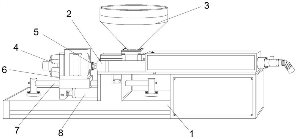
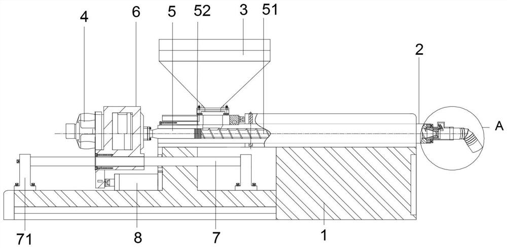
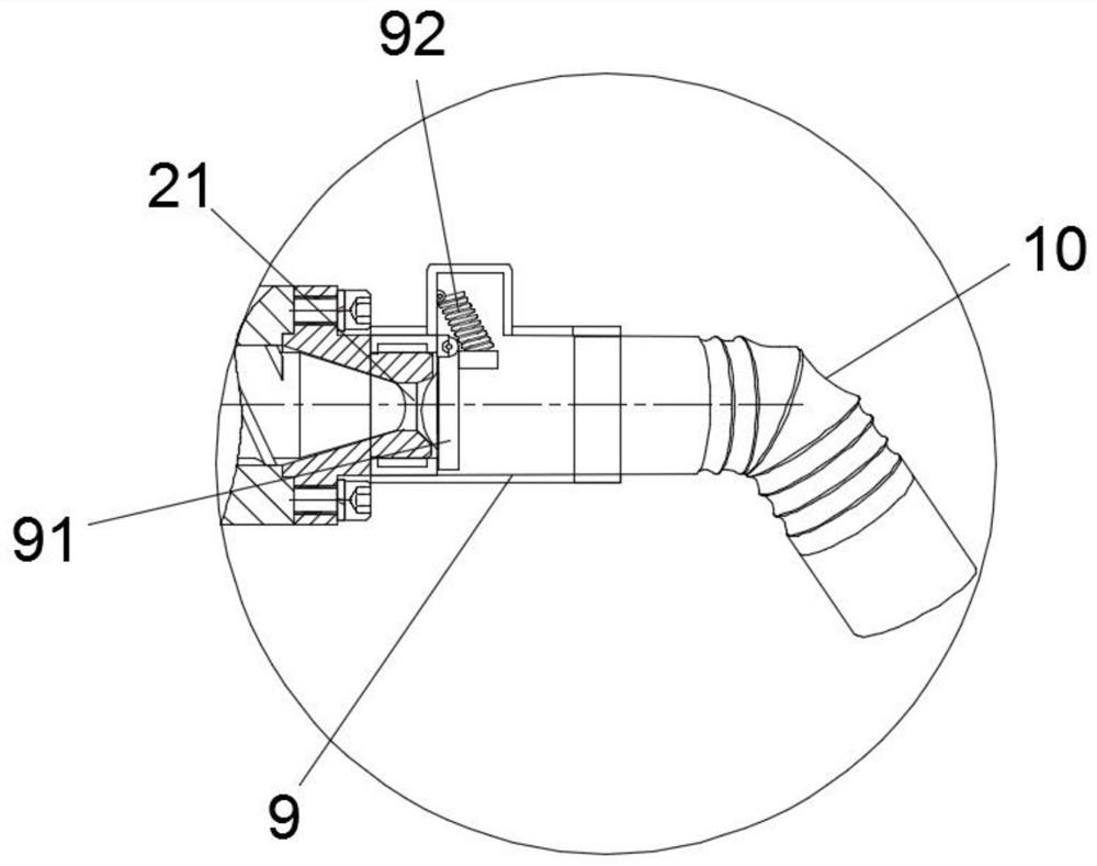
[0016] Such as Figure 1-Figure 3 As shown, the present invention provides a technical scheme of fast screw feeding equipment: a kind of fast screw feeding equipment, the structure includes a frame 1 and a feeding pipe 2 installed on the frame 1, and one end of the feeding pipe 2 is provided with Outlet 21, the middle part of the feeding pipe 2 is provided with a hopper 3, the other side of the feeding pipe 2 is provided with a drive motor 4, the shaft is connected with a rotating shaft 5, and the rotating shaft 5 can be slidably embedded in the feeding pipe 2 Inside, the frame 1 is fixed with a rectangular slide bar 7, the rectangular slide bar 7 is slidably provided with a fixed mount 6, the drive motor 4 is fixed on the fixed mount 6, and the l...


PUM


Abstract

The invention relates to the technical field of feeding equipment, in particular to rapid screw feeding equipment. The rapid screw feeding equipment comprises a rack and a feeding pipe mounted on therack. A discharge port is formed in one end of the feeding pipe, a feed hopper is arranged in the middle of the feeding pipe, a drive motor is arranged on the other side of the feeding pipe, the drivemotor is connected with a rotary shaft through a shaft, the rotary shaft is slidingly embedded into the inner side of the feeding pipe, the rack is fixedly provided with a rectangular sliding rod, the rectangular sliding rod is slidingly provided with a fixing frame, the drive motor is fixedly arranged on the fixing frame, an electric push rod is arranged on the lower side of the fixing frame, the fixing frame is connected with the rack through the electric push rod, one end of the feeding pipe is connected with a connecting pipe, the other end of the connecting pipe is connected with a telescopic pipe, the drive motor is arranged on the fixing frame, the electric push rod of the drive motor can push the fixing frame to move left and right, thus, the rotary shaft connected with the motordrives a screw to move in the feeding pipe, and the screw generates thrust forwards while carrying out spiral conveying.

Description

technical field [0001] The invention relates to the technical field of feeding equipment, in particular to a fast screw feeding equipment. Background technique [0002] Screw feeder is also called screw feeder, screw conveyor, scraper conveyor, bucket conveyor, etc. belong to conveying equipment. It has the characteristics of high conveying efficiency, safe and reliable work, simple structure, complete functions, good sealing, low noise and beautiful appearance. It is widely used in various industrial sectors, such as building materials, electric power, chemical industry, metallurgy, coal, aluminum magnesium, machinery, light industry, grain and food industry. However, the existing screw feeder is easily blocked by the accumulation and adhesion of materials at the delivery outlet of the existing screw feeder, which affects the discharge speed, and the existing outlet is usually set at one end of the conveying pipe in a straight line, and the structure is relatively rigid, w...

Claims


Application Information

Patent Timeline
Patent Type & Authority Applications(China)
IPC IPC(8): B65G33/14B65G33/38B65G47/34
CPCB65G33/14B65G33/38B65G47/34
Inventor 郭毅义
Owner 郭毅义
Why Eureka
Try Eureka