
Automatic winding device of digital printing thermal transfer printer

A thermal transfer printing machine and digital printing technology, applied in the direction of winding strips, transportation and packaging, thin material processing, etc., can solve the problem of not meeting the processing and use requirements of thermal transfer machines, and achieve a simple structure and ensure clamping. effect, the effect of increasing friction

Active Publication Date: 2020-09-11
芜湖韩大防伪科技有限公司
View PDF10 Cites 1 Cited by
  • Summary
  • Abstract
  • Description
  • Claims
  • Application Information

AI Technical Summary

Problems solved by technology

[0004] When the thermal transfer machine is processing, it is often necessary to use an automatic winding device to automatically rewind the object. During the processing of the heat transfer machine, intermittent winding is often required, and most of the existing automatic winding devices are continuous. Rewinding can not meet the processing and use requirements of thermal transfer machines

Method used


Image

  • Automatic winding device of digital printing thermal transfer printer
  • Automatic winding device of digital printing thermal transfer printer
  • Automatic winding device of digital printing thermal transfer printer

Examples


Embodiment 1

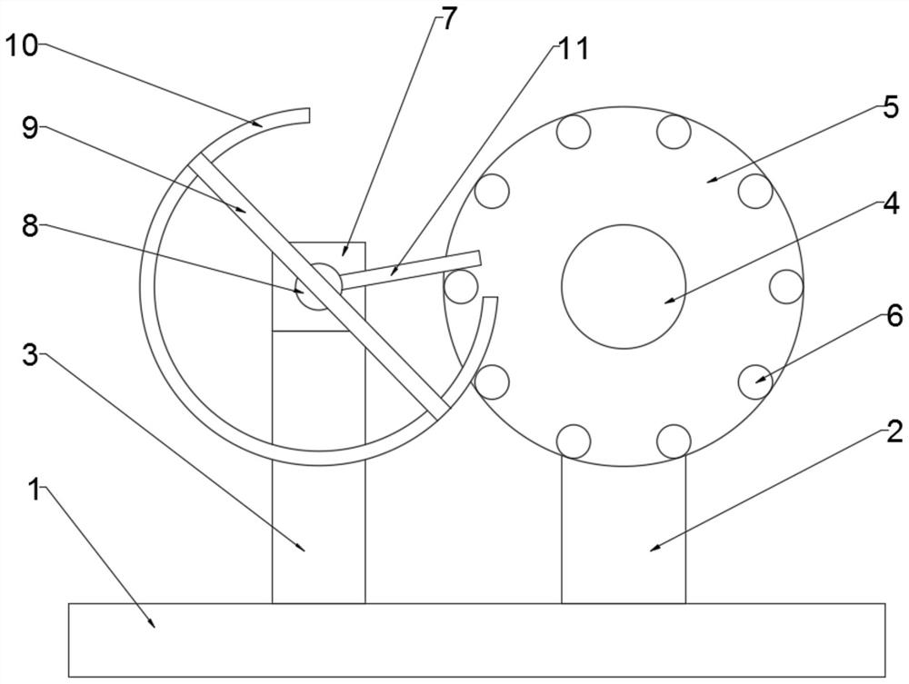
[0039] see figure 1 , an automatic winding device for a digital printing thermal transfer machine, including a base 1, a first bracket 2 vertically arranged on the right side of the upper surface of the base 1, and a fixed bracket 2 on the left side of the first bracket 2 on the upper surface of the base 1 The second bracket 3 vertically arranged, the first bracket 2 is rotatably connected with a rotating shaft 4, the outer wall of the rotating shaft 4 is sleeved with a winding roller 5, and the front side wall of the winding roller 5 is evenly distributed with a plurality of Annularly distributed cylinder 6, the top of the second support 3 is fixed with a drive motor 7, the output end of the drive motor 7 is connected with a drive shaft 8, the front end of the drive shaft 8 is fixed with a fixed rod 9 that is inclined, and the rear side wall of the fixed rod 9 A circular ring 10 is fixed on the top, an opening is provided on the circular ring 10, a driving rod 11 is fixed on ...


PUM


Abstract

The invention discloses an automatic winding device of a digital printing thermal transfer printer, and belongs to the technical field of digital printing processing. The automatic winding device of the digital printing thermal transfer printer comprises a base. A first support which is vertically arranged is fixed to the right side of the upper surface of the base, and a second support which is vertically arranged on the upper surface of the base and located on the left side of the first support. A rotating shaft is connected to the first support in a rotating mode, a winding roller is connected to the outer wall of the rotating shaft in a sleeving mode, and multiple cylinders which are distributed in a ring mode are evenly distributed on the front side wall of the winding roller. A driving motor is fixed to the top end of the second support, the output end of the driving motor is connected with a driving rotating shaft, and a fixing rod which is arranged in an inclined mode is fixedto the front end of the driving rotating shaft. A circular ring is fixed to the rear side wall of the fixing rod, an opening is formed in the circular ring, and a driving rod is fixed to the side wallof the driving rotating shaft. The purpose that automatic winding operation is intermittently conducted can be achieved, the control over the intermittence time of intermittent winding operation canbe conducted by controlling the rotating speed of the motor, the structure is simple, and the work is stable and reliable.

Description

technical field [0001] The invention relates to the technical field of digital printing processing, and more specifically, relates to an automatic winding device of a digital printing thermal transfer machine. Background technique [0002] Digital printing is printing using digital technology. Digital printing technology is a high-tech product that integrates machinery, computer, electronic information technology and gradually formed with the continuous development of computer technology. Digital printing works basically the same as inkjet printers, a technology that dates back to 1884. In 1960, inkjet printing technology entered the practical stage. In the 1990s, computer technology began to become popular, and in 1995, an on-demand inkjet digital jet printing machine appeared. The development of digital printing technology is showing a trend of all heroes rising together and a hundred flowers blooming. The technology involved in digital printing is becoming more and mo...

Claims


Application Information

Patent Timeline
Patent Type & Authority Applications(China)
IPC IPC(8): B65H18/10B65H18/02B65H75/14B65H75/28
CPCB65H18/02B65H18/10B65H75/14B65H75/28
Inventor 李玲芳
Owner 芜湖韩大防伪科技有限公司
Learn More