Structure of underwater ground anchor type marina

A ground-anchored, yacht-based technology, applied in the field of yacht wharfs, can solve the problems of reduced anti-fatigue performance of pile holders, shedding of anti-corrosion layers on the surface of guide piles, poor anti-wave performance, etc., and achieves easy promotion, low maintenance costs, and anti-fatigue good performance

Pending Publication Date: 2020-09-11
上海宏辉港务工程有限公司
View PDF0 Cites 0 Cited by
  • Summary
  • Abstract
  • Description
  • Claims
  • Application Information

AI Technical Summary

Problems solved by technology

[0002] At present, the structure of the yacht dock is mainly in the form of "floating body + guide pile + approach bridge". The floating dock of this form is mainly composed of three parts: floating body, guide pile and approach bridge. The floating body of the floating dock and the guide pile are connected by pile holders. The floating body of the wharf moves up and down along the positioning piles with the change of the water level, and there is only a small displacement relative to the revetment. The number of guide piles is generally more than two, and the number is mainly related to the size of the wharf, the plane structure and the water environment. The fixing method of the approach bridge is related to The same as the conventional form, one end of the approach bridge is fixed on the revetment in a hinged form, and the other end is equipped with a roller as a free end, which can be rolled back and forth on the barge to adjust the slope of the approach bridge as the water level chang

Method used


Image

  • Structure of underwater ground anchor type marina
  • Structure of underwater ground anchor type marina
  • Structure of underwater ground anchor type marina

Examples


Embodiment Construction

[0016] The following will clearly and completely describe the technical solutions in the embodiments of the present invention with reference to the accompanying drawings in the embodiments of the present invention. Obviously, the described embodiments are only some, not all, embodiments of the present invention. Based on the embodiments of the present invention, all other embodiments obtained by persons of ordinary skill in the art without making creative efforts belong to the protection scope of the present invention.

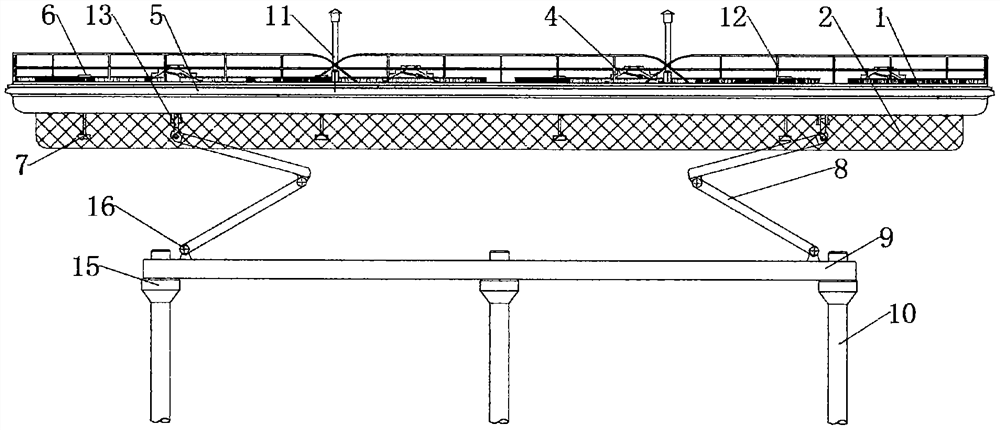
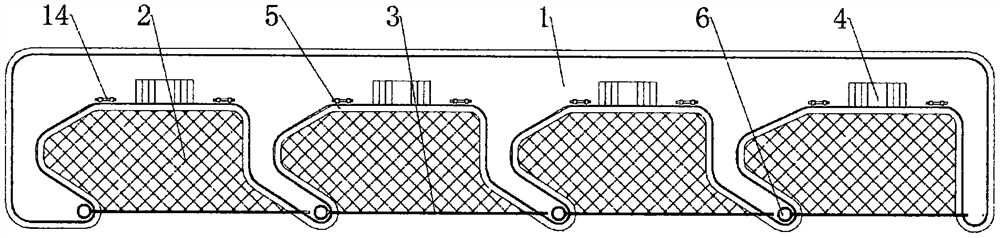
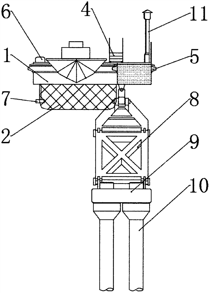
[0017] see Figure 1-5 , the present invention provides a technical solution: a structure of an underwater ground-anchored yacht wharf, including a floating body 1, a drift intercepting net 2, a dirt-blocking buoy 3, a movable adjustable gangway 4, a flexible anti-collision fender 5, and a trash-blocking Drift retractor 6, anti-wave resistance device 7, foldable strut 8, underwater concrete anchor beam 9, fixed pile foundation 10, lighting pole 11, protective ...


PUM


Abstract

The invention discloses a structure of an underwater ground anchor type marina. The structure comprises floating bodies, flotsam intercepting nets, trash holding buoys, movable adjusting accommodationladders, flexible anti-collision fenders, trash holding buoy storing and releasing devices, anti-wave resistors, foldable supporting rods, underwater concrete anchor beams, fixed pile foundations, floodlight poles, protective barriers, first hinge supports, bollards, cushion caps and second hinge supports. The protective barriers are welded around the tops of the floating bodies, a plurality of floodlight poles are arranged at the tops of the floating bodies, and the flexible anti-collision fenders are mounted around the tops of the floating bodies. The structure of the underwater ground anchor type marina is good in integrality and simple, can be modularly arranged easily according to needs and is convenient to popularize. Visual pollution of the portions, exposed to water, of guide piles is avoided, and the structure is attractive. The overall structure is good in anti-fatigue performance. By designing the flexible protective fenders, the collision force on the body of a yacht during mooring is weakened; and components are free of overwater unnecessary abrasion, the maintenance cost is low, and the economic performance is good.

Description

technical field [0001] The invention relates to the technical field of marinas, in particular to a structure of an underwater anchored marina. Background technique [0002] At present, the structure of the yacht dock is mainly in the form of "floating body + guide pile + approach bridge". The floating dock of this form is mainly composed of three parts: floating body, guide pile and approach bridge. The floating body of the floating dock and the guide pile are connected by pile holders. The floating body of the wharf moves up and down along the positioning piles with the change of the water level, and there is only a small displacement relative to the revetment. The number of guide piles is generally more than two, and the number is mainly related to the size of the wharf, the plane structure and the water environment. The fixing method of the approach bridge is related to The same as the conventional form, one end of the approach bridge is fixed on the revetment in a hinged...

Claims


Application Information

Patent Timeline
IPC IPC(8): E02B3/06E02B15/06E02B3/26
CPCE02B3/06E02B3/064E02B3/26E02B15/06Y02A10/11Y02A30/30
Inventor 熊宽旺
Owner 上海宏辉港务工程有限公司
Why Eureka
Try Eureka