SDDC pile ground structure construction method

A construction method and ground structure technology, applied in foundation structure engineering, sheet pile walls, soil protection, etc., can solve problems such as single filler, poor economy, and hole penetration, and achieve improved load-bearing capacity, improved bearing capacity, and uniform stiffness Effect

Inactive Publication Date: 2020-09-11
河南省第八建设集团有限公司
View PDF4 Cites 2 Cited by
  • Summary
  • Abstract
  • Description
  • Claims
  • Application Information

AI Technical Summary

Problems solved by technology

Among the above treatment methods for collapsible loess foundations, method (1) and method (2) have shallow treatment depths and are not suitable for sites with deep collapsible loess; method (3) has a large negative impact on the environment and is not suitable for existing It is used around buildings and urban areas; method (4) uses a single filler, and the compaction effect on the soil between piles is not ideal, and can only eliminate the subsidence of the foundation to a limited extent; method (5) is expensive to deal with, and is generally not accepted Adopted; method (6) when the ground around the site sinks and cracks when flooded, it is easy to cause "running water" to penetrate holes and affect the safety of surrounding buildings; method (7) deal with deep collapsible loess areas, especially in self-weight collapsible loess areas In the loess site, in order to overcome the adverse effects of negative friction, the required piles are long and the economy is poor
[0004] Among the above traditional treatment methods for collapsible loess foundations, especially for sites with deep self-weight collapsible loess, there is no economical and effective foundation treatment method that can meet the requirements of high-rise buildings (tall structures) for foundation bearing capacity and settlement , therefore, finding a new treatment method for collapsible loess foundation is a focus of attention of those skilled in the art

Method used


Image

  • SDDC pile ground structure construction method
  • SDDC pile ground structure construction method
  • SDDC pile ground structure construction method

Examples


Embodiment Construction

[0044] The present invention will be described in further detail below in conjunction with the accompanying drawings.

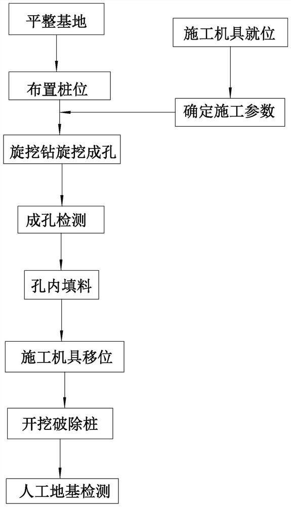
[0045] refer to figure 1 , is a kind of SDDC pile-ground structure construction method disclosed by the present invention, with reference to figure 1 , including the following steps:

[0046] (1) Leveling the base: First, excavate the foundation to be constructed. After excavation, the bottom of the foundation pit is uneven, which is not convenient for the pile driver to be in place and cannot guarantee the verticality of the pile body. The foundation is leveled by the loader.

[0047] (2) Arrangement of pile positions: measure and set out the lines, release the positions of each pile according to the design drawings, and drill holes with steel brazing to form holes. The holes require that the pile points can still be found after removing the disturbed soil layer on the surface.

[0048] (3) The construction equipment is in place: the rotary drilling drill ...


PUM


Abstract

The invention relates to an SDDC pile ground structure construction method. A rammer carries out layered tamping and compacting on the deep layer of a foundation from bottom to top, backfill is forcedto be extruded through tamping work with high kinetic energy, super pressure intensity and strong compaction, and dense pile bodies are formed. Meanwhile, the side face of the rammer generates extremely high dynamic passive earth pressure, and earth among piles is strongly compacted and reinforced. Earth around the piles is compacted to form a forced compacted area, a compacted area and a compacted influence area, so that a foundation bears high compressive pre-press, no obvious compressive deformation is generated when the treated foundation is soaked with water or loaded, and the mechanicalproperty of the foundation is improved. Under the tamping action of high kinetic energy, super pressure intensity and strong compaction on the SDDC piles, the earth stress is slowly released, and lateral restraints are generated on the earth around the piles. The lateral stress borne by the earth around the piles is slowly released after the piles are formed, the piles and the earth among the piles form a compact whole, and the treatment depth is large. The treated composite foundation is uniform in rigidity, and the bearing capacity is remarkably improved.

Description

technical field [0001] The invention relates to the technical field of foundation construction, in particular to an SDDC pile-ground structure construction method. Background technique [0002] Loess foundation treatment problems are often encountered in Northwest and North China, usually including low-humidity collapsible loess with the main purpose of eliminating or reducing the damage of collapsible deformation, and at the same time need to improve the foundation bearing capacity, and high-humidity soft loess (Especially saturated loess, which is mostly transformed from collapsible loess saturated with water, and the saturation degree Sr>80%) is a foundation treatment problem aimed at improving the bearing capacity of the foundation and reducing harmful compression deformation. Since the engineering characteristics of the latter are mostly similar to those of ordinary cohesive soils, the compression deformation of the foundation should be mainly considered, and can be ...

Claims


Application Information

Patent Timeline
Patent Type & Authority Applications(China)
IPC IPC(8): E02D5/46E02D3/08
CPCE02D3/08E02D5/46
Inventor 李振彬万鹏辉韩学华张佩轩侯丹青
Owner 河南省第八建设集团有限公司
Why Eureka
Try Eureka