Connector and radiation tomographic imaging apparatus

a radiation tomographic imaging and connection technology, applied in the direction of coupling contact members, coupling device connections, tomography, etc., can solve the problems of reducing the space available for connection work, difficult to connect the electrodes to one another at high precision, and difficult to fix the board, etc., to achieve easy fixation, small thickness, and large thickness

Inactive Publication Date: 2006-04-18
GE MEDICAL SYST GLOBAL TECH CO LLC
View PDF14 Cites 10 Cited by
  • Summary
  • Abstract
  • Description
  • Claims
  • Application Information

AI Technical Summary

Benefits of technology

[0013]It is therefore an object of the present invention to provide a connector and a radiation tomographic imaging apparatus by which a board can be easily fixed with sufficient rigidity and the board can be easily inserted / removed, thereby facilitating maintenance work.
[0015]According to the present invention, by inserting the clamp member through the second insert opening into the socket portion, the surface of the clamp member comes into contact with the surface of the retaining member and the side wall of the socket portion running along a surface of the retaining member to press the retaining member in the socket portion, whereby the board received in the socket portion is fixed. Since the retaining member is formed to have a smaller thickness at one end near the second insert opening than that at the other end, and the clamp member is formed to have a larger thickness at one end near the second insert opening than that at the other end, the other end of the socket portion on the opposite side of the second insert opening can be easily pressed, whereby the board is fixed with uniform rigidity.
[0017]According to the present invention, by inserting the clamp member through the second insert opening into the socket portion, the surface of the clamp member comes into contact with the other surface of the retaining member and the side wall of the socket portion running along a surface of the retaining member to press the retaining member in the socket portion, whereby the board received in the socket portion is fixed to connect the first and second electrodes. Since the retaining member is formed to have a smaller thickness at one end near the second insert opening than that at the other end, and the clamp member is formed to have a larger thickness at one end near the second insert opening than that at the other end, the socket portion can be easily pressed at the other end on the opposite side of the second insert opening, whereby the board is fixed with uniform rigidity to connect the first and second electrodes.
[0018]Therefore, the present invention provides a connector and a radiation tomographic imaging apparatus by which a board can be easily fixed with sufficient rigidity and the board can be easily inserted / removed, thereby facilitating maintenance work.

Problems solved by technology

With the conventional thermal compression bonding, however, the increased compactness of the electrodes reduces the space available for the connection work, and it becomes difficult to connect the electrodes to one another at high precision.
With the conventional connectors, the high compactness of the electrodes makes it difficult to connect between the electrodes and to fix the boards on which the electrodes are formed to the connector with sufficient rigidity.
Moreover, when maintenance is carried out on an X-ray detector array constituted of a plurality of X-ray detector modules, it suffices to replace only the one malfunctioning X-ray detector module in the small space where the plurality of boards are disposed; but with the conventional connection by thermal compression bonding, the modules cannot be made removable, and with the conventional connectors, the space for insertion / removal work is small because the plurality of boards are present, and the insertion / removal work is difficult to do.
As described above, in the conventional X-ray CT apparatus, one example of a radiation tomographic imaging apparatus, as the number of detector elements in the X-ray detector is increased in line with the need for improved image quality and imaging speed, the electrodes are arranged at higher density, and it becomes difficult to fix the boards to the connector with sufficient rigidity and to insert / remove the board into / from the connector because of the small space available for disposing the boards, which makes it difficult to do maintenance work.

Method used


Image

  • Connector and radiation tomographic imaging apparatus
  • Connector and radiation tomographic imaging apparatus
  • Connector and radiation tomographic imaging apparatus

Examples


Embodiment Construction

[0030]Exemplary embodiments in accordance with the present invention will now be described in detail with reference to the accompanying drawings.

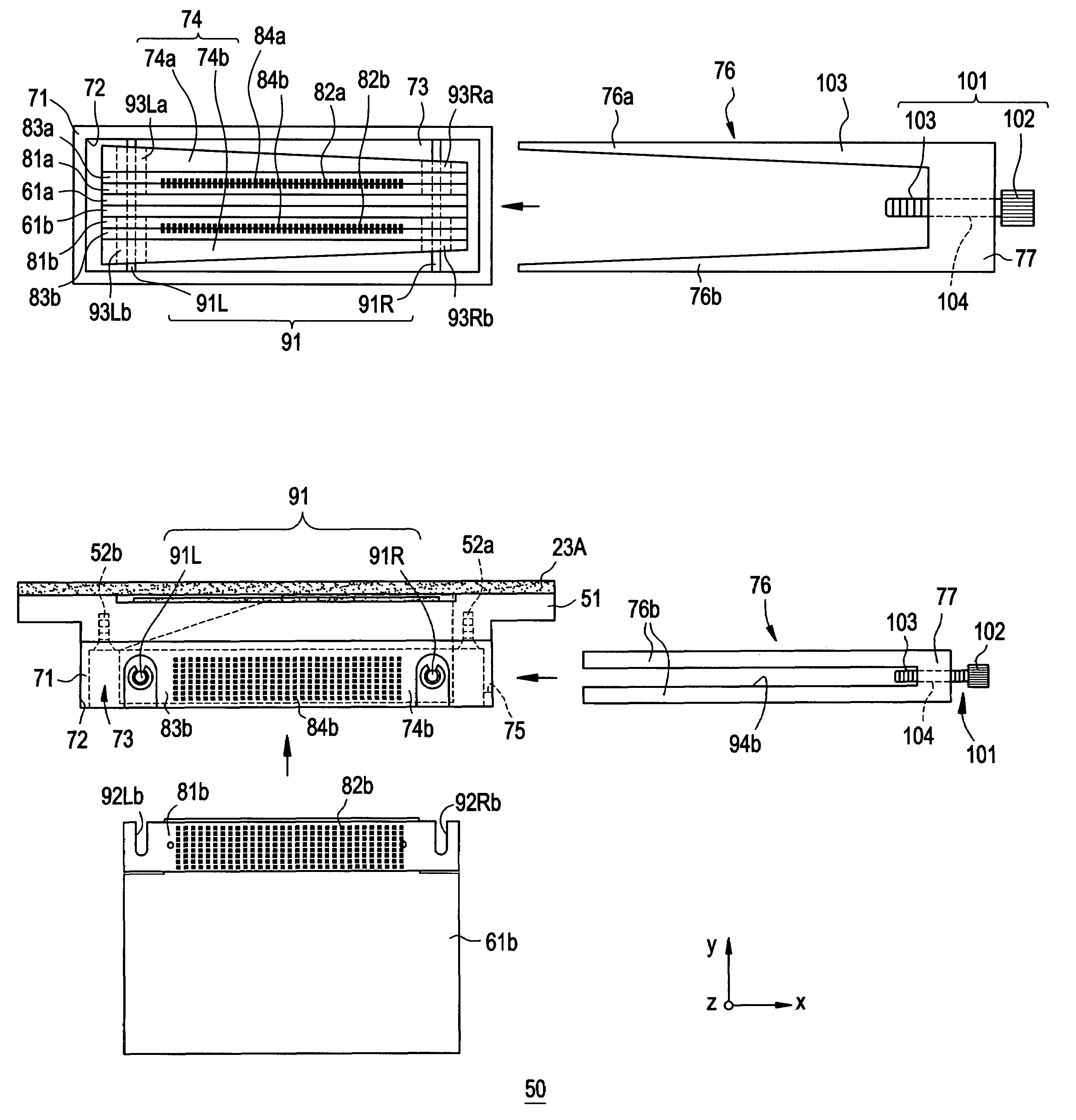
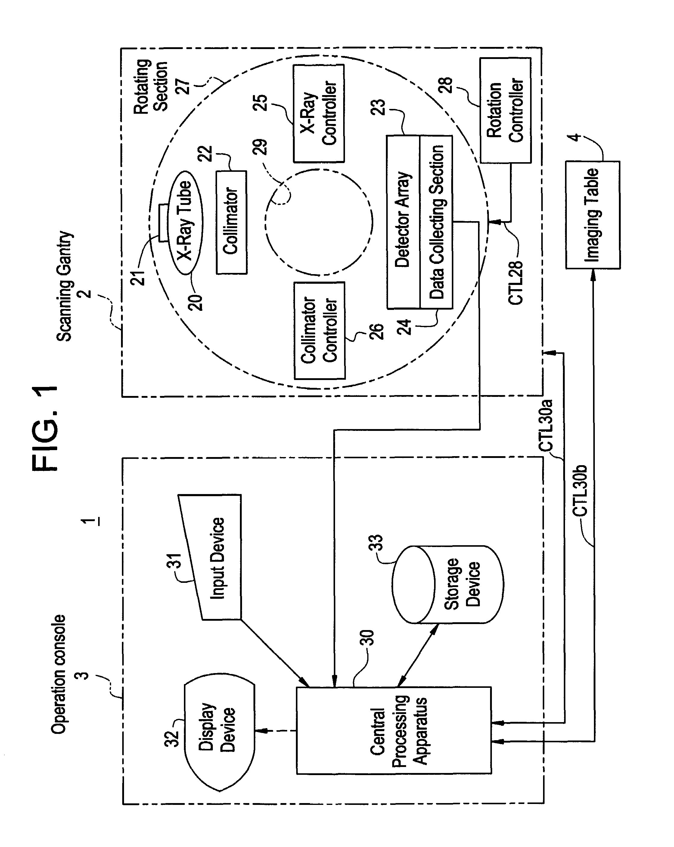
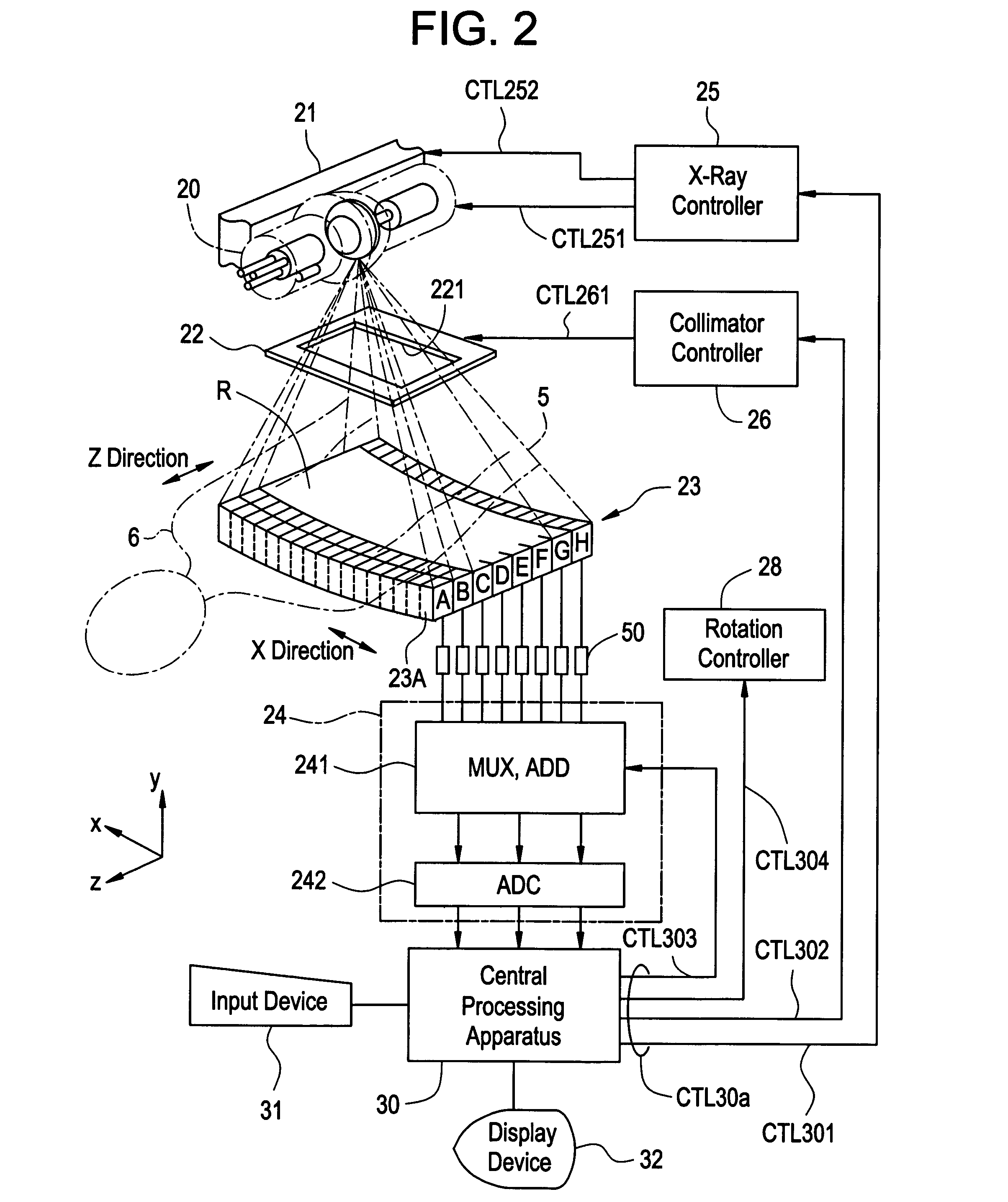
[0031]First, the configuration of a radiation tomographic imaging apparatus of an embodiment in accordance with the present invention will be described. FIG. 1 is a block diagram showing the overall configuration of an X-ray CT apparatus 1 that is an embodiment of the radiation tomographic imaging apparatus in accordance with the present invention, and FIG. 2 is a configuration diagram showing a main portion in the X-ray CT apparatus 1 that is an embodiment of the radiation tomographic imaging apparatus in accordance with the present invention.

[0032]As shown in FIG. 1, the X-ray CT apparatus 1 of the present embodiment comprises a scan gantry 2, an operation console 3, and an imaging table 4.

[0033]The scan gantry 2 comprises an X-ray tube 20, an X-ray tube moving section 21, a collimator 22, an X-ray detector array 23, a data collecting sec...


PUM


Abstract

A connector includes a clamp member inserted through a second insert opening into a socket portion such that the surfaces of the clamp member come into contact with the surface of a retaining member and the side wall of the socket portion running along a surface of the retaining member to press the retaining member, and such that a plurality of boards received in the socket portion are fixed to connect a plurality of first electrodes with a plurality of second electrodes.

Description

CROSS REFERENCE TO RELATED APPLICATION[0001]This application claims the benefit of Japanese Application No. 2003-362097 filed Oct. 22, 2003.BACKGROUND OF THE INVENTION[0002]The present invention relates to a connector and a radiation tomographic imaging apparatus, and particularly to a connector applied to detecting means in which a plurality of detector elements for detecting radiation and outputting projection data are disposed, and a radiation tomographic imaging apparatus employing such a connector.[0003]Known radiation tomographic imaging apparatuses include an X-ray CT (computed tomography) apparatus that employs X-ray radiation to produce an image representing a cross-sectional plane of a subject to be imaged. The X-ray CT apparatus is used in a wide variety of applications including medical and industrial applications with a human body or an inanimate object as a subject to be imaged.[0004]The X-ray CT apparatus scans the subject to be imaged around the body axis of the subj...

Claims


Application Information

Patent Timeline
Patent Type & Authority Patents(United States)
IPC IPC(8): H01R13/15A61B6/03H01R12/70H01R12/79H01R13/629
CPCA61B6/032A61B6/4233A61B6/4411H01R12/7005H01R13/629H01R23/68H01R12/7064A61B6/025A61B6/03
Inventor SAWAYA, TAKUJI
Owner GE MEDICAL SYST GLOBAL TECH CO LLC
Why Eureka
Try Eureka