Lay-out for splicing strips comprising cords

a technology of connecting strips and splicing strips, which is applied in the field of splicing strip layout schemes, can solve the problems of not being able to use strips with mainly axial reinforcement, not being practicable, and not being able to achieve the effect of strip breaking load, easy integration into a strip, and no difference in bending behavior

Active Publication Date: 2014-12-16
BEKAERT ADVANCED CORDS AALTER NV
View PDF22 Cites 10 Cited by
  • Summary
  • Abstract
  • Description
  • Claims
  • Application Information

AI Technical Summary

Benefits of technology

[0022]It is therefore a first object of the invention to provide a splice that shows a substantially uniform bending stiffness in combination with sufficient strength retention and a splice section substantially equal to that of the strip. It is an object of the invention to provide a splice that can sustain at least half of the strength of the strip. It is further object of the invention to improve plain stepped splices outside the known ‘organ pipe’ or ‘fir tree’ lay-outs.
[0051]Arrangements with increased common length will have a larger anchoring surface than arrangements with shorter common lengths. As |qi+1−qi|≧n it follows that the common length is always larger or equal than nLgroup. Hence, increasing ‘n’ will result in increased common length which results in better anchoring and hence a better splice.
[0059]By adapting the Group length Lgroup one can therefore tune the splice strength according to need. When the Group length Lgroup is larger than N / n times the critical length Lc a breaking load of the part of the splice in the Group that is above half of the strength of the part of the strip in the Group can be expected. A splice with a Group with ‘n’ equal to ‘nmax’ can therefore be made within the shortest possible length. Or put differently: for a given Lgroup, the Group arrangements with the highest ‘n’ will contribute most to the total strength of the splice. By increasing the splice length—but without the need of going higher than (2N / n)×Lc—a splice strength larger than 50%, or larger than 55%, 60%, 70%, 80% or 90% of the breaking load of the strip can be attained which is surprisingly high for this kind of splice.
[0060]The splice can be easily incorporated into a strip and shows virtually no difference in bending behavior compared to the strip itself. Therefore two strips connected by the inventive splice can be considered as a single strip and fall within the same inventive concept.

Problems solved by technology

However, this is not practical.
Hence, making practical splices is always compromising between the different requirements (A) to (E) mentioned above.
It can not be used for strips with mainly axial reinforcement (the clamps tear out).
Such splices are difficult to discern from the strip itself in terms of bending stiffness, axial stiffness and section.
However, they show a lower strength compared to ‘Interlaced stepped splices’.

Method used


Image

  • Lay-out for splicing strips comprising cords
  • Lay-out for splicing strips comprising cords

Examples


Embodiment Construction

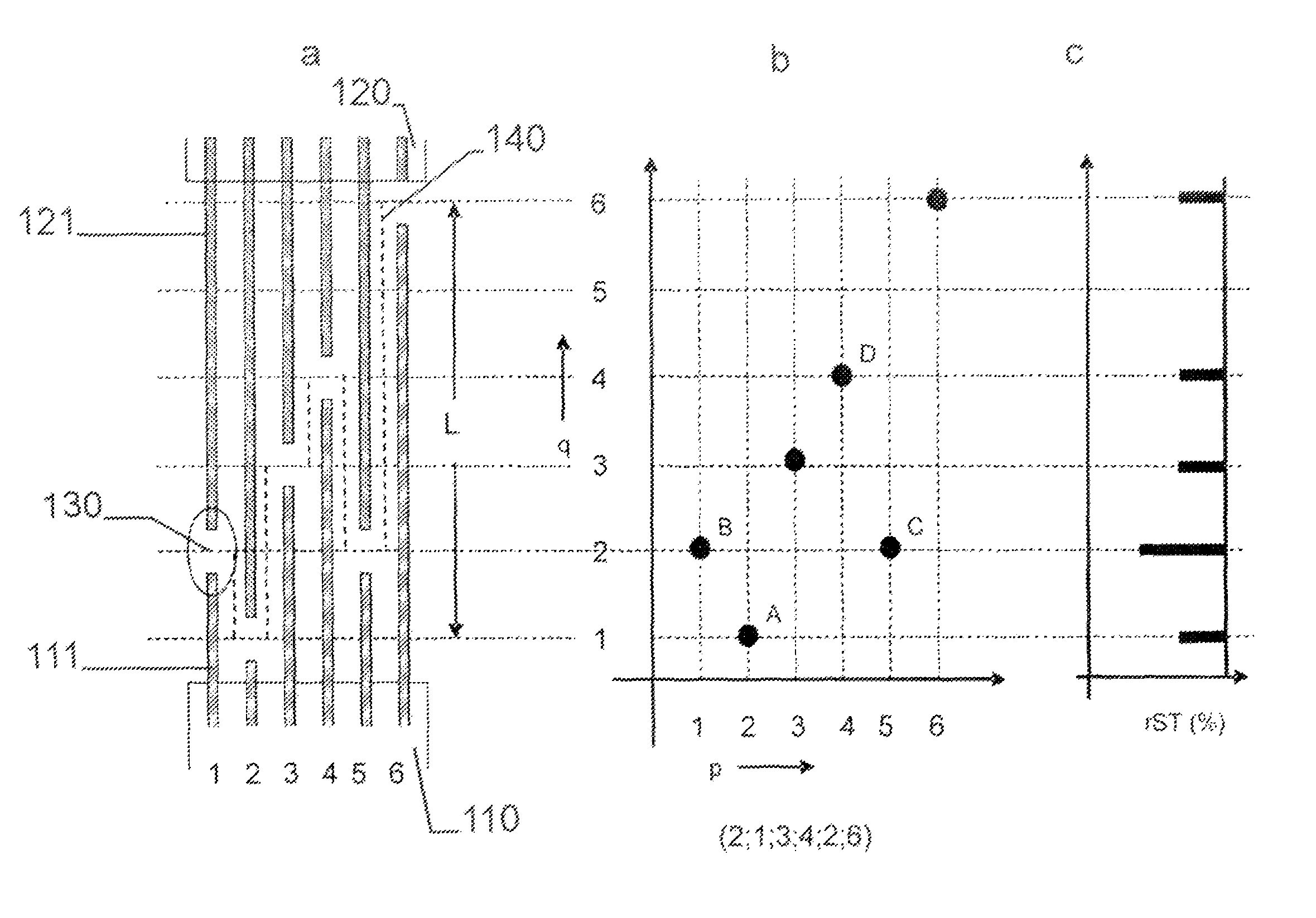
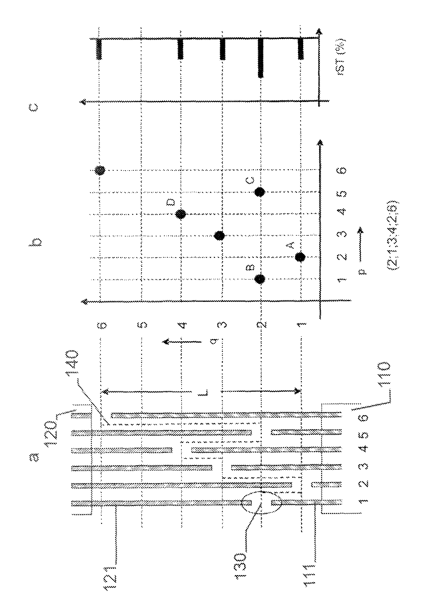
[0066]In a first step for implementing the invention one must find those arrangements which fulfil the requirement of having a taxi-distance between abutments larger than four, or five or six, possibly up to nmax. How can now such an optimum arrangement be found in this universe of NN different arrangements?

[0067]Obviously, not the way to go is to enumerate all possible arrangements NN and test each pair in the arrangement whether the distance requirement is met. Per test there are N×(N−1) / 2 comparisons to be done. Such a procedure is only possible for very small N.

[0068]Alternatively, one could try by trial and error in order to find an arrangement that suits the requirement. This could be done for example by means of a Monte-Carlo type of procedure: generate N random numbers in the set of 1 to N and check whether they fulfil the requirement. This could be further improved by introducing a ‘stochastic cooling’ algorithm that accepts changes in the arrangement that increase pairs-wi...


PUM

PropertyMeasurementUnit
diameteraaaaaaaaaa
tensile strengthaaaaaaaaaa
lengthaaaaaaaaaa

Abstract

A plain stepped splice lay-out scheme is presented that can be used for splicing strips to one another that comprise longitudinally arranged cords. The strips can take the form of a conveyor belt, transmission belt, timing belt, elevator belt, a rubber track or a reinforcing strip. The splice is optimised for uniform bending stiffness and maximum strength retention. The cross section of the strip and the splice are substantially equal: there is no increase in thickness or width at the splice. The splice lay-out is characterised by the fact that the abutments (130)—those positions where cord ends (111, 121) meet—are positioned sufficiently far away from one another and by preference as far away from one another as possible. Preferred embodiments in terms of length common between cords of the different strips and local strength are given.

Description

TECHNICAL FIELD[0001]The invention relates to a lay-out scheme for splices connecting strips reinforced with lengthwise arranged cords.BACKGROUND ART[0002]In many technical applications flexible belts or ‘strips’ are used. Such strips generally are made from elongated strength members, which will be called ‘cords’ hereinafter, arranged parallel to one another in the plane of the strip. In many cases the strips are encased in a polymer material or ‘matrix’ although other binding methods such as weaving or knitting are also possible to hold the cords together. The strips have a substantially oblong cross section. The anisotropic nature of such strips, being flexible in a direction perpendicular to the plane of the cords and rigid in that plane while being strong mainly in the lengthwise direction, makes them particularly suited to take up tension in static or dynamic applications.[0003]In dynamic applications strips can be found as conveyor belts (to transfer materials), transmission ...

Claims


Application Information

Patent Timeline
Patent Type & Authority Patents(United States)
IPC IPC(8): F16G3/10B29C65/00
CPCB29C66/4324B29C66/73921B29C66/43B29C66/1142B29C66/72141F16G3/10B29C66/7212B29C66/71B29C66/964Y10T24/1664B29C65/48B29C66/1248B29C66/244B29C66/73941B29K2021/00B29K2305/12B29K2077/00B29K2309/08B29K2277/10B29K2023/04B29K2023/10B29K2075/00B29K2305/00B29K2311/00B29K2023/06B29K2023/12
Inventor DE SMET, ANNELEENVERVAECKE, FREDERIK
Owner BEKAERT ADVANCED CORDS AALTER NV
Why Eureka
Try Eureka