Energy storage battery module and echelon utilization system

An energy storage battery module and energy storage battery technology, which is applied in the direction of battery pack components, circuits, electrical components, etc., can solve the problems that the positive and negative terminals of the energy storage battery module are easily short-circuited, so as to avoid short-circuit faults, The effect of widening the distance

Pending Publication Date: 2020-09-11
CHINA HUADIAN ENG +1
View PDF0 Cites 2 Cited by
  • Summary
  • Abstract
  • Description
  • Claims
  • Application Information

AI Technical Summary

Problems solved by technology

[0005] Therefore, the technical problem to be solved by the present invention is that the positive and negative poles of the energy storage battery modules are ...

Method used


Image

  • Energy storage battery module and echelon utilization system
  • Energy storage battery module and echelon utilization system

Examples


Embodiment 1

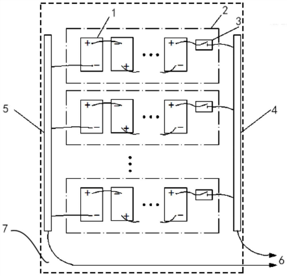
[0038] Such as figure 2 As shown, the embodiment of the present invention provides an energy storage battery module, which includes: a plurality of energy storage battery modules 2 , a positive bus bar 4 and a negative bus bar 5 .

[0039]The energy storage battery module 2 is composed of several energy storage battery cells 1 connected in series and parallel. The energy storage battery module 2 is formed with a positive output terminal and a negative output terminal, and there is a certain distance between the positive output terminal and the negative output terminal. The positive output ends of all the energy storage battery modules 2 are all connected to the positive bus bar 4 , and the negative output ends of all the energy storage battery modules 2 are all connected to the negative bus bar 5 . Since there is a certain distance between the positive output terminal and the negative output terminal, there is also a certain distance between the positive bus bar 4 and the neg...

Embodiment 2

[0050] The present invention also provides a cascade utilization system, which includes: the energy storage battery module and the battery rack 7 as described in the above embodiments. The battery rack 7 is suitable for placing the energy storage battery module 2 in the above embodiment.

[0051] With such a setting, technicians can place the energy storage battery unit 1 on the battery rack 7 assembled on site during on-site construction, and the technicians can also install the energy storage battery unit 1 according to the needs of different application scenarios and according to actual conditions. Flexible series-parallel connection to form energy storage battery modules 2 with different powers. Moreover, it is also convenient for technicians to replace the energy storage battery unit 1 at any time later. Therefore, the replaced energy storage battery cells 1 can be resourced, and the cascaded utilization of the energy storage battery cells 1 can be realized. It avoids t...


PUM


Abstract

The invention discloses an energy storage battery module and an echelon utilization system. The energy storage battery module comprises: a plurality of energy storage battery modules which are formedby series-parallel connection of a plurality of energy storage battery monomers; a positive electrode busbar connected with the positive electrode output ends of the plurality of energy storage battery modules; and a negative electrode busbar connected with the negative electrode output ends of the plurality of energy storage battery modules. According to the arrangement, the positive electrode output ends of the energy storage battery modules are connected with the positive electrode busbar, and the negative electrode output ends of the energy storage battery modules are connected with the negative electrode busbar, so that multiple energy storage battery modules are connected without flexible wires; and after a plurality of energy storage battery modules are connected through the positive electrode busbar and the negative electrode busbar, a short circuit condition cannot occur due to a certain distance between the positive electrode busbar and the negative electrode busbar, so thata short circuit fault between the positive electrode and the negative electrode of each energy storage battery module is solved.

Description

technical field [0001] The invention relates to the technical field of large-scale energy storage, in particular to an energy storage battery module and a cascade utilization system. Background technique [0002] At present, in the field of megawatt-scale large-scale energy storage, the applied energy storage battery modules are usually installed in the battery box, and the energy storage battery module will be compactly integrated in the closed shell of the battery box. In this kind of battery box, the energy storage battery module usually uses connecting cables to connect the positive and negative terminals of adjacent battery cells in series and parallel, and finally connect the positive and negative terminals of the energy storage battery module to the terminal through the cable. . [0003] Because in the field of large-scale energy storage, many battery sub-boxes equipped with energy storage battery modules are required, and for saving space and facilitating operation,...

Claims


Application Information

Patent Timeline
IPC IPC(8): H01M2/20H01M2/34
CPCY02E60/10
Inventor 祁希萌刘军红李艳红王兴兴
Owner CHINA HUADIAN ENG
Why Eureka
Try Eureka