Easy tube replacing device for body cavity drainage

A technology of drainage tube and body cavity, which is applied in the field of body cavity drainage and easy-change tube device, which can solve the problems of difficult insertion of guide wire, easy displacement or slipping out, time-consuming and laborious problems, etc., and achieves increased fixed area, safe and reliable use, and fixed Good results

Pending Publication Date: 2020-09-15
PEKING UNIV SHENZHEN HOSPITAL
View PDF0 Cites 0 Cited by
  • Summary
  • Abstract
  • Description
  • Claims
  • Application Information

AI Technical Summary

Problems solved by technology

[0004] Specifically, on the one hand, the tube body is elongated. After the tube body is inserted into the patient's body cavity, the front end of the tube body is not very fixed, so that it is easy to shift or slip out when it is slightly pulled. On the other hand, when the tube body of the corresponding drainage tube is blocked by fluid in the body or when it has been used for a specified period of time, it needs to be replaced. The traditional tube replacement operation is generally to use a guide wire to extend into the patient's body cavity along the corresponding tube body Drainage site, then pull out the corresponding tube body and insert a new drainage tube body to be replaced along the corresponding guide wire
Related tube replacement operations are very common. However, when the tube body of the corresponding drainage tube is blocked, the guide wire used is difficult to insert. At this time, it is necessary for the medical staff to slowly move the guide wire back and forth until the corresponding drainage tube is found. The tube body of the tube is not completely blocked, so that the operation of inserting the guide wire is time-consuming and laborious. When the tube body of the corresponding drainage tube is completely blocked by fluid in the body, it needs to be re-diagnosed under ultrasound and other imaging. Putting tubes on patients, in this way, will increase medical costs, and simultaneously increase the workload of medical staff and increase the discomfort of patients such as pain

Method used


Image

  • Easy tube replacing device for body cavity drainage
  • Easy tube replacing device for body cavity drainage
  • Easy tube replacing device for body cavity drainage

Examples


Embodiment Construction

[0061] The technical solution of the present invention will be described in detail below in conjunction with the accompanying drawings and specific embodiments, so as to understand the essence of the present invention more clearly and intuitively.

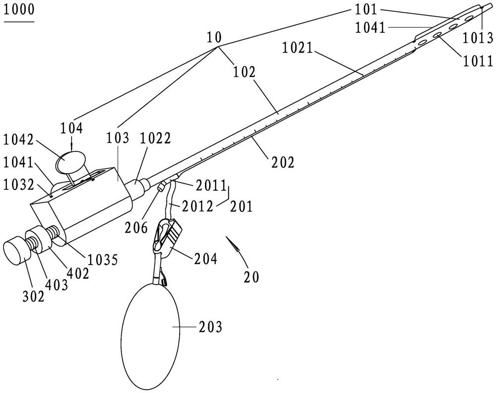
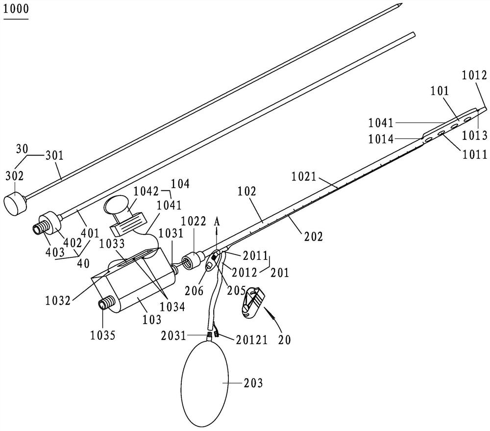
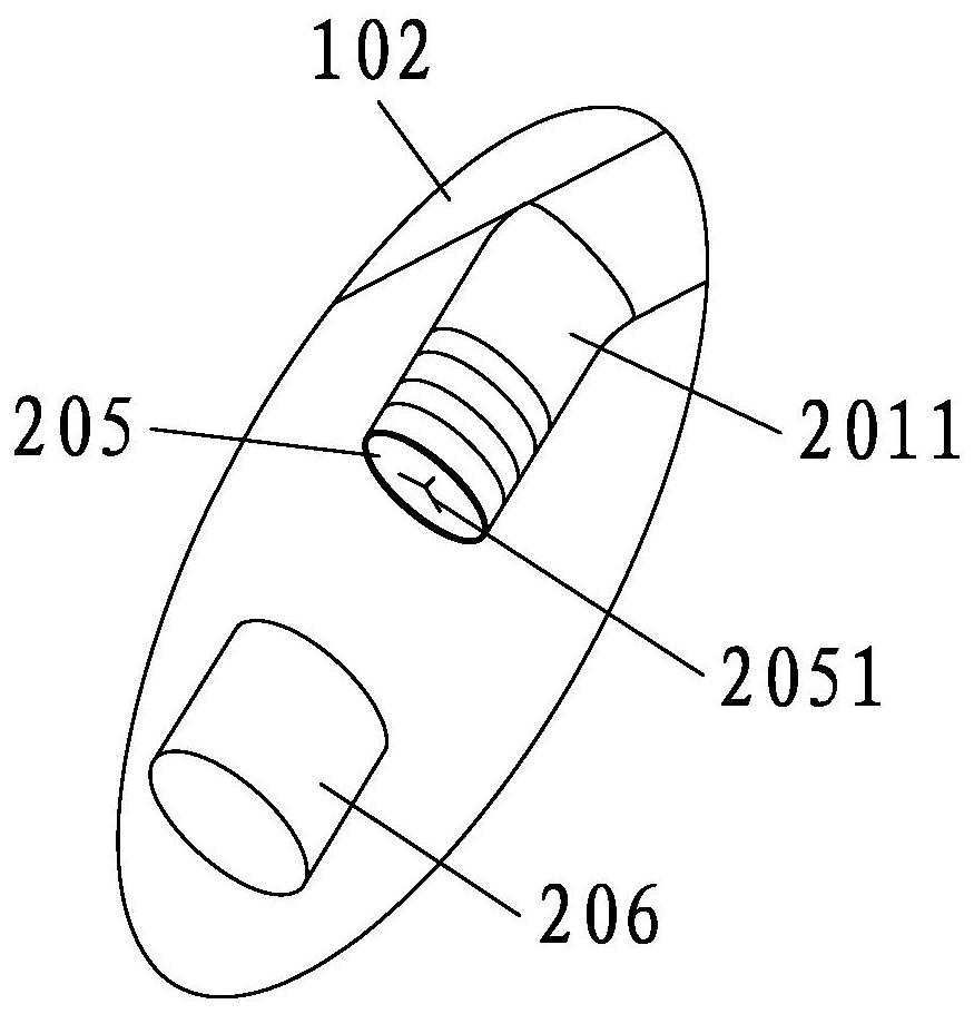
[0062] figure 1 It is a schematic diagram of the overall structure of the easy-to-change tube device for body cavity drainage of the present invention; figure 2 It is an exploded view of the easy-to-change tube device for body cavity drainage of the present invention; image 3 yes figure 2 In, the enlargement of A; Figure 4 yes figure 2 , the enlarged view of the current limiting clamp; Figure 5 It is a schematic diagram of the overall structure of the connection between the guide pin and the guide sleeve in this embodiment; Figure 6 In this embodiment, after the drainage tube is placed in the patient's body cavity, the front end of the tube head is rolled into a ring shape in use; Figure 7 yes Figure 6 Among them, a...


PUM

PropertyMeasurementUnit
Lengthaaaaaaaaaa

Abstract

The invention discloses an easy tube replacing device for body cavity drainage. The device comprises a drainage tube and a tube replacing component, wherein the drainage tube comprises a tube head, atube body, a tube base and a tube head pulling and rolling component. The pipe replacing component comprises a guide pipe and an elastic film strip; the sum of the length of the guide pipe and the length of the elastic film strip is smaller than the length of the tube body; the guide pipe is fixed on the rear-end outer wall of the tube body; two longer side edges of the elastic film strip are fixed on the outer wall of the tube body along the length direction of the tube body, and the rear end is fixed on the outer wall of the front end of the guide tube to form a guide wire insertion channelbetween the inner surface and the outer wall of the tube body; in a natural state, the elastic film strip is attached to the tube body, and when the guide wire is inserted into the guide wire insertion channel, the elastic film strip deforms to open the guide wire insertion channel. The easy tube replacing device has the advantages that after a tube is placed in a patient, the tube head of the drainage tube can be driven to be pulled and rolled into a ring shape by manually controlling the tube head pulling and rolling component, the drainage tube can be well stumbled by body cavity tissue ofthe patient, fixation is good, when the tube replacing component is used for tube replacing operation, the tube replacing speed is high, the workload of medical staff can be relieved, and medical costis reduced.

Description

technical field [0001] The invention relates to the technical field of medical care products, in particular to a body cavity drainage easy-change tube device. Background technique [0002] In major hospitals, a built-in drainage tube is often inserted into the patient's body cavity for external drainage of body cavity fluid, such as peritoneal effusion drainage and pleural effusion drainage. [0003] Commonly used drainage tubes mainly include a tube body and a socket connected to the outside of the corresponding tube for external drainage. Although drainage tubes with corresponding structures are widely used, they still have certain defects and deficiencies; [0004] Specifically, on the one hand, the tube body is elongated. After the tube body is inserted into the patient's body cavity, the front end of the tube body is not very fixed, so that it is easy to shift or slip out when it is slightly pulled. On the other hand, when the tube body of the corresponding drainage tu...

Claims


Application Information

Patent Timeline
IPC IPC(8): A61M25/00A61M25/01A61B17/34A61M25/04
CPCA61B17/3403A61B17/3415A61B2017/3413A61M25/0021A61M25/0043A61M25/0169A61M25/04A61M2025/0008
Inventor 钟洁愉
Owner PEKING UNIV SHENZHEN HOSPITAL
Why Eureka
Try Eureka