Bar chamfering machine and control method thereof

A control method and chamfering machine technology, applied in the direction of automatic control devices, manufacturing tools, metal processing machinery parts, etc., can solve the problems of poor chamfering quality, high labor intensity, and low processing efficiency, and achieve the goal of finishing difficult problems, improve processing quality, and reduce labor intensity

Inactive Publication Date: 2020-09-15
SGIS SONGSHAN CO LTD
View PDF4 Cites 2 Cited by
  • Summary
  • Abstract
  • Description
  • Claims
  • Application Information

AI Technical Summary

Problems solved by technology

For this reason, many enterprises adopt different measures to grind and chamfer the ends of the bar: such as portable grinder grinding, fixed grinder grinding, machine tool turning, etc., but the results cannot meet the requirements of the user. The main problems are: (1) The processing efficiency is low, and the chamfering of the processed thin bar products cannot be completed in time, resulting in a large backlog of products; (2) The quality of the chamfering is poor, especially when it is processed by grinding wheel grinding. At this time, the straightness and centering of the bar rotation cannot be guaranteed, and the burrs cannot be completely removed; (3) the labor intensity is high, and the working environment of the workers is harsh; (4) when the grinding method is used for chamfering, the bar The swinging of the end will cause a large impact on the grinding wheel, which will easily cause the grinding wheel to break and fly out, posing a great safety hazard

Method used


Image

  • Bar chamfering machine and control method thereof
  • Bar chamfering machine and control method thereof
  • Bar chamfering machine and control method thereof

Examples


Embodiment Construction

[0028] The present invention will be described in detail below in conjunction with the accompanying drawings and embodiments.

[0029] It is worth noting that the orientation words such as "up" and "down" involved in this article are all determined relative to the perspective of the drawings, and are only for the convenience of description, and cannot be understood as limitations on the technical solution.

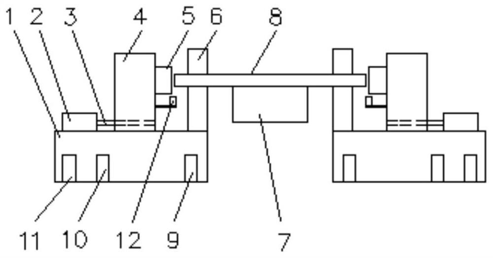
[0030] see figure 1 , a bar chamfering machine, including:

[0031] The body 1, the body 1 includes the left and right bodies 1 and is respectively arranged on the left and right sides of the feeding mechanism 7, the body 1 is provided with guide rails, and the cutting assembly 5 is slidably connected to the guide rails; the sensor limit control assembly is fixedly connected;

[0032] The cutting assembly 5 includes a rotary cutter cylinder, which is fixedly connected to a rotary drive member, and the rotary drive member is dynamically connected to the sliding drive membe...

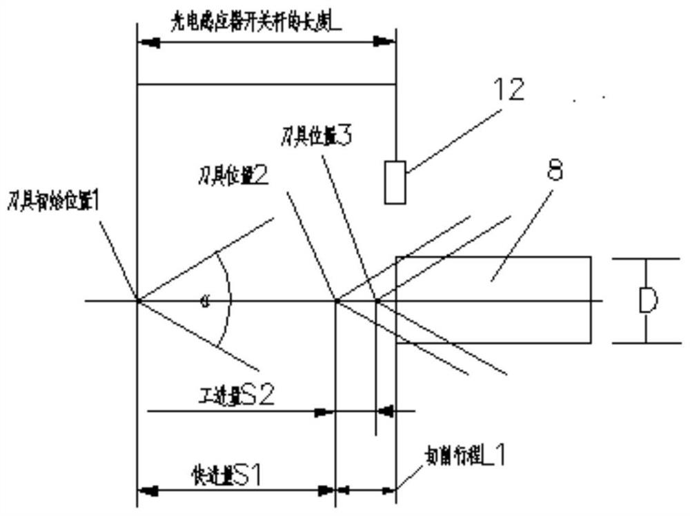
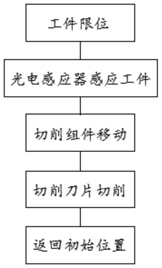

PUM


Abstract

The invention relates to a bar chamfering machine. The bar chamfering machine comprises machine bodies, wherein the machine bodies comprise a left machine body and a right machine body which are arranged on the left side and the right side of a feeding mechanism, the machine bodies are slidably connected with cutting assemblies and fixedly connected with sensor limiting control assemblies, rotaryknife cylinders are fixedly connected with rotary driving pieces, the rotary driving pieces are in power connection with sliding driving pieces, the sensor limiting control assemblies and clamping andpositioning assemblies are located on the machine bodies and are closest to the bar, photoelectric sensors are fixed to the rotary driving pieces and move synchronously along with the rotary drivingpieces, and the photoelectric sensors are electrically connected with PLC processors. According to the bar chamfering machine, the problem of bar finish machining is well solved, meanwhile, the laborintensity of workers is greatly reduced, the working environment is improved, and the surface machining quality of long and thin bars is effectively improved.

Description

technical field [0001] The invention relates to the technical field of a plate control method, more specifically, it relates to a bar chamfering machine and a control method thereof. Background technique [0002] At present, in the production process of slender bar products in domestic steel fine line enterprises, due to the influence of mechanical cutting, the end of the bar is prone to burrs, flashes, and protrusions, while the bar finishing unit and the user unit Higher and stricter requirements are put forward for the surface quality of material products. For this reason, many enterprises adopt different measures to grind and chamfer the ends of the bar: such as portable grinder grinding, fixed grinder grinding, machine tool turning, etc., but the results cannot meet the requirements of the user. The main problems are: (1) The processing efficiency is low, and the chamfering of the processed thin bar products cannot be completed in time, resulting in a large backlog of ...

Claims


Application Information

Patent Timeline
Patent Type & Authority Applications(China)
IPC IPC(8): B23B5/16B23Q15/013B23Q7/00B23Q3/06
CPCB23B5/16B23B5/165B23B5/167B23Q3/064B23Q7/00B23Q15/013
Inventor 巫献华杨家满陈听雨
Owner SGIS SONGSHAN CO LTD
Why Eureka
Try Eureka