Ultrasonic welding mould

A technology of ultrasonic welding and moulds, which is applied in the field of mechanical processing, can solve the problems of affecting the yield rate, concentrated heating of the door panel, and the yield rate cannot meet the requirements, etc., and achieve the effects of accurate positioning reference, improved application rate, and large heat dissipation area

Pending Publication Date: 2020-09-15
沈阳市常春汽车零部件有限公司
View PDF0 Cites 0 Cited by
  • Summary
  • Abstract
  • Description
  • Claims
  • Application Information

AI Technical Summary

Problems solved by technology

[0002] Ultrasonic welding is a technology commonly used in mechanical processing. At the same time, ultrasonic welding will generate huge heat for the welded objects, and the welding requirements for the welded parts on the car door panel are even stricter. The previous working method is to process the parts that need to be welded sequentially. , this welding method increases the process and processing time, and at the same time, what is more serious is that the inconsistency of each welding positioning reference leads to the failure of the yield to meet the requirements, and if multiple parts on the door panel are welded at the same time, the door panel will be concentrated due to the characteristics of ultrasonic welding Heating also affects the yield rate, so there is a lack of a high-precision ultrasonic welding mold with good heat dissipation in the prior art

Method used


Image

  • Ultrasonic welding mould
  • Ultrasonic welding mould
  • Ultrasonic welding mould

Examples


Embodiment Construction

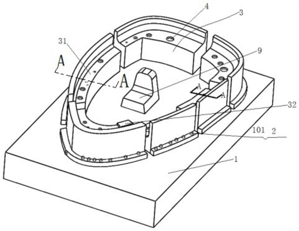
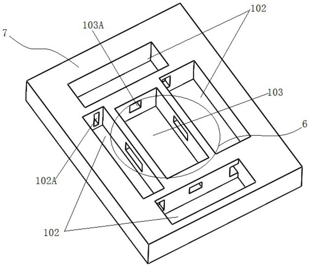
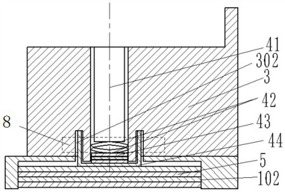
[0016] The present invention will be specifically described below in conjunction with the accompanying drawings. As shown in the figure, an ultrasonic welding mold includes a positioning seat 1, and the positioning seat is provided with uniformly distributed threaded holes 101, and the positioning module 3 is fixed on the screw thread of the base by bolts 2. In the hole, the inside of the positioning module 3 is provided with a groove 31 for fixing the door panel, and the grooves 31 together form a spliced ​​door panel shape, and a welding module assembly 4 is also provided on the plane of the groove, and the welding module assembly It includes a heat-conducting copper column 41 plugged into the groove, and a bent plate 42 is provided under the heat-conducting copper column, and the bent plate is also arranged in the groove 31; Block 43, the heat conduction cover 44 arranged on the outside of the heat dissipation block is screwed into the threaded groove 302 below the positioni...


PUM


Abstract

The invention discloses an ultrasonic welding mould. The ultrasonic welding mould is characterized in that a positioning seat is provided with evenly-distributed threaded holes, a positioning module is fixed in threaded holes of a base through bolts, a groove used for fixing a door plate is formed in a positioning module, a welding module assembly is further arranged at the position of the plane of the groove, and the welding module assembly comprises a heat conduction copper column inserted into the groove; a bending plate is arranged below the heat conduction copper column, a heat dissipation block is further arranged below the bending plate, and a heat conduction cover is connected into a threaded groove in the lower portion of the positioning module in a threaded mode; and rectangulargrooves are formed below the positioning seat, heat exchange fins are arranged in the rectangular grooves, and a central rectangular groove is formed in the center of the bottom of the positioning seat. The ultrasonic welding mould has the advantages that a convex edge and a positioning block ensure that the positioning reference of the welding procedure is more accurate, the structure of the positioning seat ensures that the structure of a heat dissipation part is consistent even if the appearance structure of the door plate is changed, and a central heat dissipation area and an edge heat dissipation areas are adopted, so that the heat dissipation area is larger, and meanwhile heat dissipation is more uniform.

Description

technical field [0001] The invention relates to the field of mechanical processing, in particular to a welding device for a car door panel. Background technique [0002] Ultrasonic welding is a technology commonly used in mechanical processing. At the same time, ultrasonic welding will generate huge heat for the welded objects, and the welding requirements for the welded parts on the car door panel are even stricter. The previous working method is to process the parts that need to be welded sequentially. , this welding method increases the process and processing time, and at the same time, what is more serious is that the inconsistency of each welding positioning reference leads to the failure of the yield to meet the requirements, and if multiple parts on the door panel are welded at the same time, the door panel will be concentrated due to the characteristics of ultrasonic welding Heating also affects the yield, so the prior art lacks a high-precision ultrasonic welding mo...

Claims


Application Information

Patent Timeline
Patent Type & Authority Applications(China)
IPC IPC(8): B23K37/04B23K20/10B23K20/26
CPCB23K20/10B23K20/26B23K37/0443
Inventor 张斌
Owner 沈阳市常春汽车零部件有限公司
Why Eureka
Try Eureka