
Sepharose gel plate punching structure

A technology of agarose gel and pore structure, which is applied in the direction of sampling, measuring devices, instruments, etc. It can solve the problems of affecting the experimental judgment results, not being able to make different numbers of holes, time-consuming and labor-intensive, etc., to prevent mutual pollution and high practicability , the effect of simple operation

Active Publication Date: 2020-09-15
许子涵
View PDF6 Cites 1 Cited by
  • Summary
  • Abstract
  • Description
  • Claims
  • Application Information

AI Technical Summary

Problems solved by technology

In the process of realizing the present invention, the inventor has found that there are at least the following problems in the prior art. The glass tube punching method first puts the solidified agarose gel plate on the punching template drawing, and then uses a hollow glass tube to solidify the agarose gel. The gel plate is punched, and finally the agarose in the hole is picked out. However, when the glass tube is inserted into the agarose gel plate skewed when punching the hole, it will affect the experimental judgment result. After the glass tube is punched, the hole needs to be picked out Agarose inside, very time-consuming and labor-intensive
Comb punching method is to insert a comb into the gel before the agarose gel coagulates. After the gel is solidified, pull out the comb to form a hole. Since the number of teeth of the comb is fixed, it can only be used on the agarose gel plate. A fixed number of holes can be formed on the surface, and different numbers of holes cannot be made according to the actual needs of the experiment.

Method used


Image

  • Sepharose gel plate punching structure
  • Sepharose gel plate punching structure
  • Sepharose gel plate punching structure

Examples


Embodiment Construction

[0020] This part will describe the specific embodiment of the present invention in detail, and the preferred embodiment of the present invention is shown in the accompanying drawings. Each technical feature and overall technical solution of the invention, but it should not be understood as a limitation on the protection scope of the present invention.

[0021] In the description of the present invention, it should be understood that it involves orientation descriptions, such as center, longitudinal, transverse, length, width, thickness, up, down, front, back, left, right, vertical, horizontal, top, bottom , inner, outer, clockwise, counterclockwise, axial, radial, circumferential, etc. indicate the orientation or positional relationship based on the orientation or positional relationship shown in the drawings, and are only for the convenience of describing the present invention and simplifying the description, and It is not to indicate or imply that the device or element refer...


PUM


Abstract

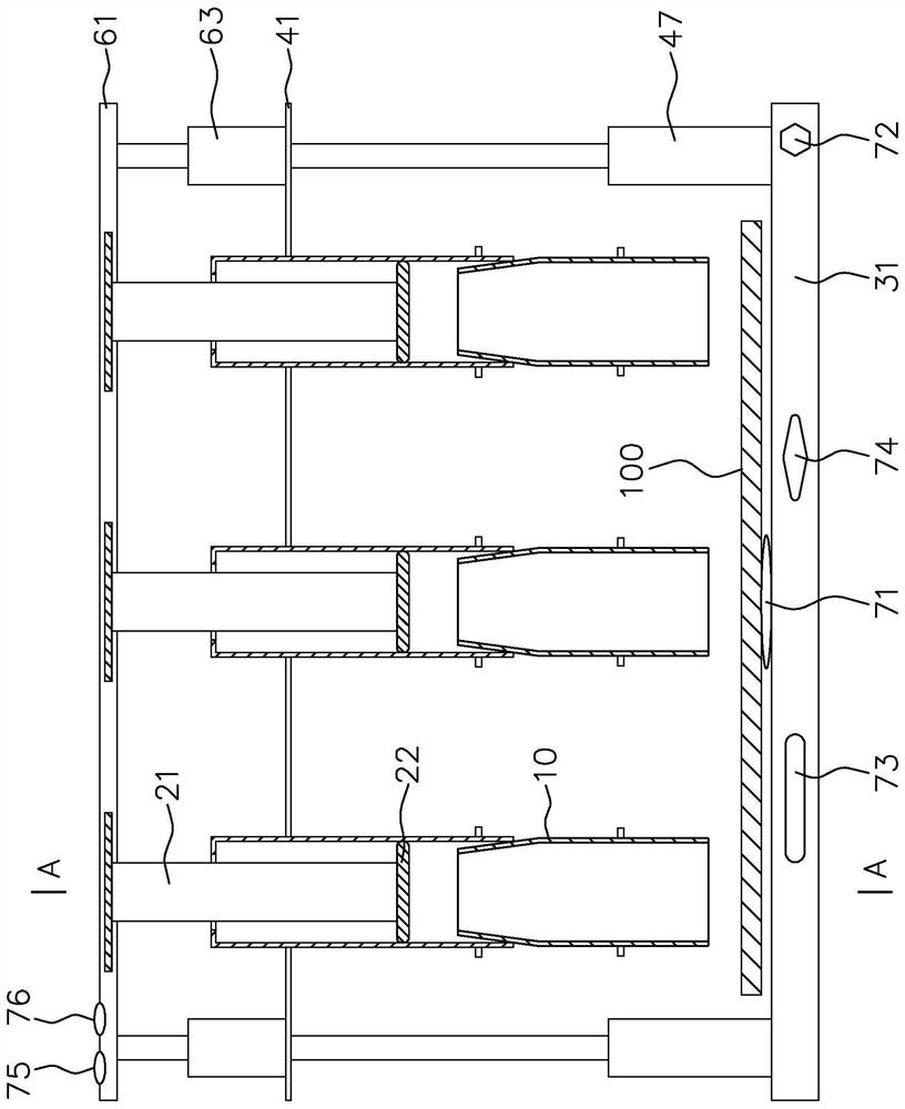
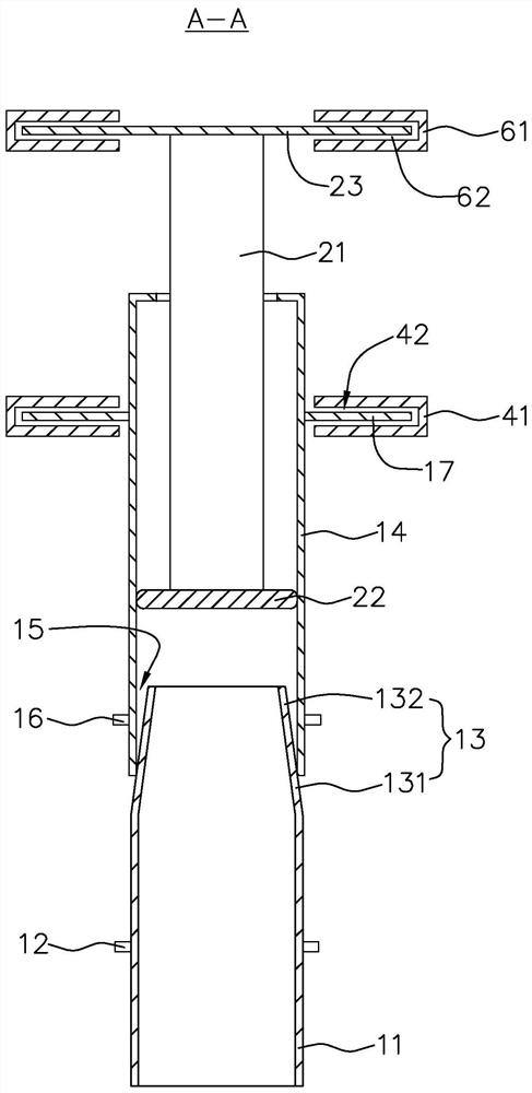
The invention discloses a sepharose gel plate punching structure. The punching structure comprises a supporting stand, a lifting unit, and a plurality of needle tubes; the supporting stand comprises atop plate, a supporting plate and a bottom plate which are arranged in sequence from top to bottom; the bottom plate is provided with a placing surface for placing a sepharose gel plate; the liftingunit comprises at least one supporting plate lifting assembly and at least one top plate lifting assembly, the supporting plate lifting assembly drives the supporting plate to go up and down and the top plate lifting assembly drives the top plate to go up and down; negative pressure assemblies are arranged inside the needle tubes; and each of the negative pressure assemblies comprises a piston which moves up and down inside a punching tube and a piston rod with the lower end connected with the piston, the upper end of the piston rod penetrates through the punching tube and is fixed with the top plate, a through hole is formed in the upper end of the punching tube and is for the piston rod to penetrate, and the needle tube is fixed with the supporting plate. The punching structure can meetactual requirements of different experiments and rapidly punch needed holes.

Description

technical field [0001] The invention relates to the technical field of experimental equipment, in particular to an agarose gel plate punching structure. Background technique [0002] Gel electrophoresis has always been one of the routine experiments in the field of biological research. Researchers can directly understand information such as nucleic acid purity and fragment size through electrophoresis experiments. Holes are punched on the gel plate, and the samples to be tested are placed in the punched holes. [0003] Commonly used punching methods mainly include glass tube punching method and comb punching method. In the process of realizing the present invention, the inventor has found that there are at least the following problems in the prior art. The glass tube punching method first puts the solidified agarose gel plate on the punching template drawing, and then uses a hollow glass tube to solidify the agarose gel. The gel plate is punched, and finally the agarose in...

Claims


Application Information

Patent Timeline
Patent Type & Authority Applications(China)
IPC IPC(8): B26F1/02B26F1/14B26D7/18B26D5/00B26D7/26G01N1/28
CPCB26F1/02B26F1/14B26D7/1863B26D5/005B26D7/2628B26D7/2614G01N1/286G01N2001/2873Y02P60/21
Inventor 许子涵杨卓霖
Owner 许子涵
Learn More