
Parking cylinder

A cylinder and parking technology, which is applied to bicycle accessories, axle suspension devices, springs, etc., can solve the problems of easy oil leakage at the connection between the oil pipe and the solenoid valve, inability to automatically lock the frame movement, and low degree of automation. Easy to automate and intelligent, realize the effect of automation and intelligence, not easy to heat

Pending Publication Date: 2020-09-15
ZHEJIANG XINGCHEN PNEUMATIC
View PDF0 Cites 0 Cited by
  • Summary
  • Abstract
  • Description
  • Claims
  • Application Information

AI Technical Summary

Problems solved by technology

This parking method is cumbersome and requires manual pulling of the handbrake cable for parking braking. The degree of automation is low, and when the frame is tilted too much when driving at a low speed or making a large turn, it cannot automatically lock the frame, which is relatively safe. Difference
The other is to set a hydraulic damping telescopic oil cylinder between the frame and the rocker arm, connect the oil ports at both ends of the cylinder to the same oil storage tank through the oil pipe to form a hydraulic circuit, and then set a solenoid valve on the oil pipe, When parking, the solenoid valve is energized to close an oil chamber of the oil cylinder, stop the piston rod, fix the position of the frame and the rocker arm, and maintain the balance of the car body. However, this technical solution needs to use a solenoid valve when closing the oil chamber. The power is relatively large, and the coil heat is serious. After working for a long time, the coil is easy to burn out, causing inconvenience in maintenance, and the connection between the oil pipe and the solenoid valve is prone to oil leakage.

Method used


Image

  • Parking cylinder
  • Parking cylinder
  • Parking cylinder

Examples


Embodiment Construction

[0022] The present invention will be further described below in conjunction with accompanying drawing:

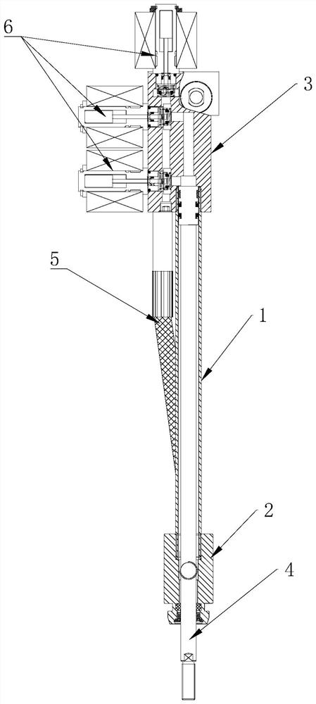
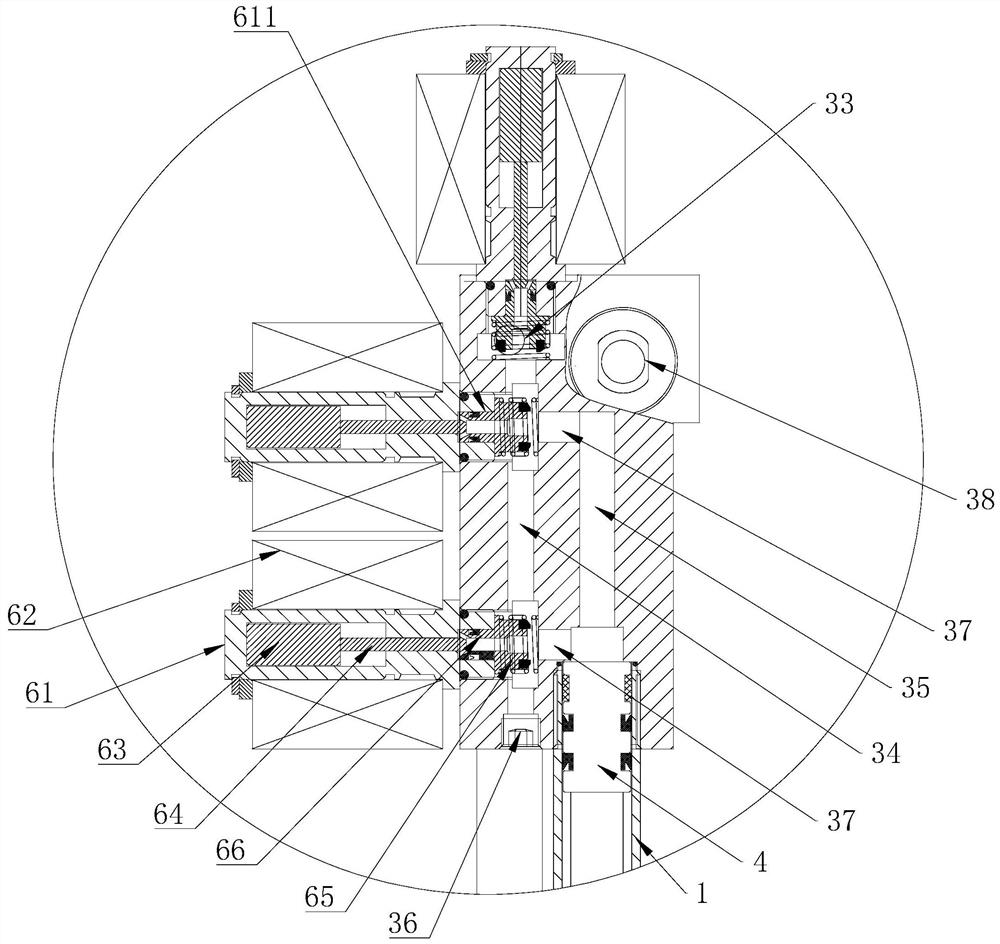
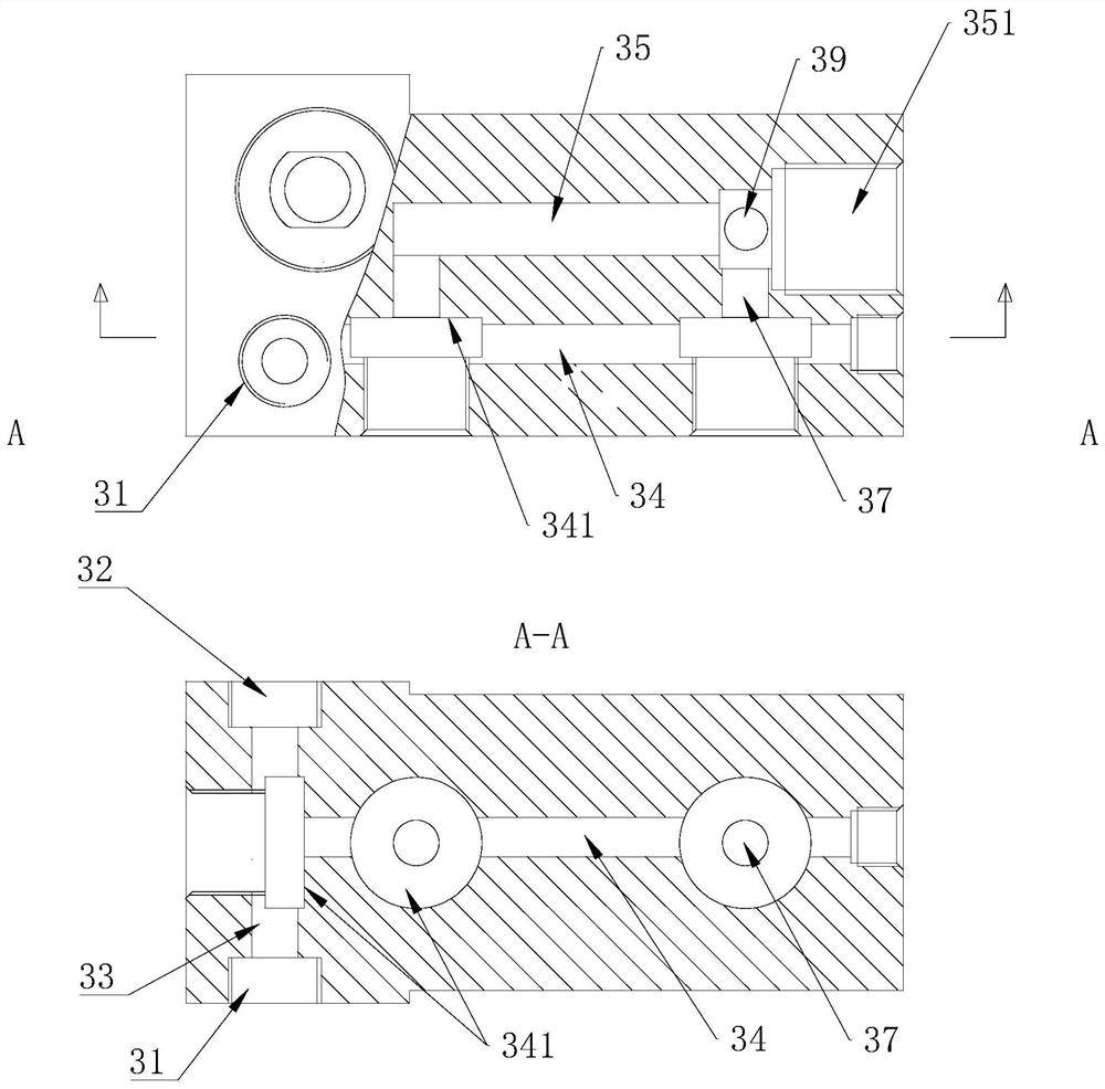
[0023] With reference to accompanying drawing: a kind of parking cylinder in the present embodiment comprises cylinder body 1, and the left and right ends of described cylinder body 1 is provided with front cover 2 and rear cover 3, and described cylinder body 1 is provided with piston rod 4, One end of the piston rod 4 is sealingly and slidingly connected with the inner wall of the cylinder body 1, and the other end of the piston rod 4 protrudes from the front cover 2. The rear cover 3 is provided with an oil inlet 31 and an oil return port 32 which communicate with each other. An oil outlet 21 is provided, and the oil outlet 21 and the oil return port 32 are connected through the oil pipe 5. The oil inlet 31 is connected to an external oil storage tank, and the back cover 3 is provided with a return passage 33, an injection Flow channel 35 and main flow channel 34, the tw...


PUM


Abstract

A parking cylinder comprises a cylinder block. A front cover and a rear cover are arranged at a left end and a right end of the cylinder block. A piston rod is arranged in the cylinder block; an oil outlet is arranged in the front cover; the oil outlet is connected with an oil return port through an oil pipe; the oil inlet is connected with an external oil storage tank; a backflow channel, a flowinjection channel and a main flow channel are arranged in the rear cover; two ends of the backflow channel are connected with the oil inlet and the oil return port; and one end of the main flow channel is connected with the backflow channel, at least two subchannels are arranged between the main flow channel and the flow injection channel, two ends of each subchannel are connected with the main flow channel and the flow injection channel, one end of the flow injection channel is connected with an inner cavity of the cylinder block, and electromagnetic valves are arranged at three forks betweenthe main flow channel and the backflow channel and between the main flow channel and the subchannels. In the invention, parking can be conveniently carried out through electric control when an inverted three-wheeled vehicle is parked, power consumed by each electromagnetic valve during braking is relatively low, a coil is not easy to burn out, and a service life is long.

Description

technical field [0001] The invention relates to the field of oil cylinder equipment, in particular to a parking cylinder. Background technique [0002] Three-wheeled motorcycles are more common in life. They are used to carry people and loads. In a car, the steering axis adjusts the direction by controlling the steering of the two front wheels. During the steering process of the motorcycle, in order to prevent the front wheel on the other side from being lifted off the ground when the vehicle is tilted to one side, the three-wheel Two rocking arms are usually arranged on the two front wheels of the motorcycle. When the inverted three-wheeled motorcycle in the prior art is parked, one is that the user turns on the handbrake switch, and the handbrake switch controls the handbrake pump to lock the handbrake plate through the handbrake line and the control plate, so that the rocker arm and the head pipe cannot be rotated relative to each other, thereby It is ensured that the c...

Claims


Application Information

Patent Timeline
Patent Type & Authority Applications(China)
IPC IPC(8): B62K25/04F16F9/19F16F9/32F16F9/34F16F9/36
CPCB62K25/04F16F9/19F16F9/3242F16F9/3207F16F9/34F16F9/36
Inventor 林兴湖
Owner ZHEJIANG XINGCHEN PNEUMATIC
Learn More