Supercharge Your Innovation With Domain-Expert AI Agents!

3D protective film capable of being subjected to heat setting or UV irradiation setting

A protective film and heat setting technology, applied in the direction of film/sheet adhesives, adhesives, etc., can solve complex problems, reduce unlocking sensitivity, cumbersome production process, etc., achieve streamlining and optimization, improve process yield and production Efficiency, guaranteed sensitivity effect

Pending Publication Date: 2020-09-15
HENGSHAN JIACHENG NEW MATERIAL
View PDF0 Cites 4 Cited by
  • Summary
  • Abstract
  • Description
  • Claims
  • Application Information

AI Technical Summary

Problems solved by technology

[0003] Most of the protective films of the existing curved screen mobile phones that use fingerprint unlocking under the screen use the optical protective film of the SRF substrate. The production process of the protective film material is complicated, and the SRF substrate has a certain polarization angle. Fixed-angle die-cutting, because the angle accuracy of all products after die-cutting cannot be guaranteed, it is prone to problems of poor fit and reduced unlocking sensitivity after matching with the mobile phone screen. In addition, the transverse tear strength of the SRF substrate is extremely poor. Hot bending is easy to break, resulting in poor stability in mass production, and its production process is cumbersome, including multiple steps such as finding polarization angle, adjusting typesetting, die-cutting, hot bending, and laminating
There are also some curved screen mobile phones that use fingerprint unlocking under the screen to use zero deflection angle PET substrate or TPU substrate as the protective film, but the loss of zero deflection angle PET is extremely high, and it needs heat bending to shape after die-cutting small pieces, and the process yield is low. , low production efficiency, and poor mass production; while the TPU substrate has poor embossing resistance and cannot meet the application needs of consumers.

Method used


Image

  • 3D protective film capable of being subjected to heat setting or UV irradiation setting
  • 3D protective film capable of being subjected to heat setting or UV irradiation setting
  • 3D protective film capable of being subjected to heat setting or UV irradiation setting

Examples


Embodiment 1

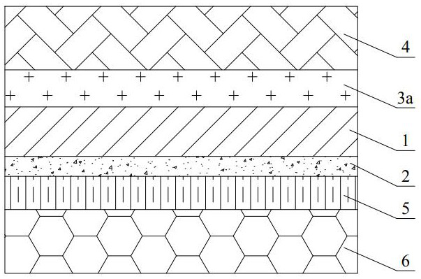
[0027] Such as figure 1 As shown, the 3D protective film that can be heat-set or UV-irradiated and set includes a protective film body. The protective film body includes an optical film substrate 1. The lower surface of the optical film substrate 1 is coated with a base film layer 2. The base film layer The shrinkage rate of 2 is higher than that of the optical film substrate 1. The optical film substrate 1 is a TPU or PMMA film that is cast or coated, and the base film layer 2 is coated on the surface of the optical film substrate 1 and passed through UV. Cured or thermally cured TPU or acrylic material, the upper surface of the optical film substrate 1 is coated with a layer of self-repairing coating 3a, and a layer of PET protective film 4 is compounded on the self-repairing coating 3a, and the lower surface of the base film layer 2 is coated with Covered with a layer of exhaust adhesive layer 5, the lower surface of the exhaust adhesive layer 5 is compounded with a layer o...

Embodiment 2

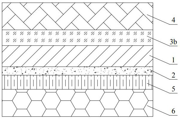
[0038] like figure 2 As shown, the difference between this embodiment and embodiment 1 is that the structure of the self-healing coating 3a is replaced by the structure of the hardened anti-scratch layer 3b, that is, the structure between the optical film substrate 1 and the PET protective film 4 is a hardened anti-scratch layer. Scratch coat 3b, wherein the hardened scratch-resistant layer 3b has a thickness of 1-5um, a water drop angle ≥ 108°, and a dynamic friction coefficient u ≤ 0.1. The 3D protective film of this structure can tear off the PET release film 6 and the PET protective film 4 Afterwards, it is pasted on the screen of the mobile phone. The top hardened scratch-resistant coating 3b can have good anti-fingerprint and scratch-resistant effects. The specific material can be selected from common hardened scratch-resistant coatings on the market. In this embodiment , the wear resistance of the hardened scratch-resistant coating 3b formed by coating can meet ≥2500 t...

Embodiment 3

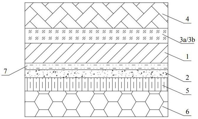
[0044] The difference between this embodiment and embodiment 1 or embodiment 2 is that the anti-blue light structure is added, which specifically includes the following three types of structures: 1. image 3 As shown, the protective film body also includes a layer of anti-blue light layer 7, which is located between the optical film substrate 1 and the base film layer 2; two, as Figure 4 As shown, the protective film body also includes a layer of anti-blue light layer 7, and the anti-blue light layer 7 is located between the base film layer 2 and the exhaust adhesive layer 5; 3. The anti-blue light layer is not added separately, but is placed in the protective film body A blue light absorber is added in any layer of the structure. The above-mentioned blue light absorber can be selected from existing blue light absorbers on the market, and the present application does not specifically limit it, and the specific structure of the anti-blue light layer 7 can also be a separate co...


PUM

PropertyMeasurementUnit
Thicknessaaaaaaaaaa
Breaking strengthaaaaaaaaaa
Thicknessaaaaaaaaaa

Abstract

The invention discloses a 3D protective film capable of being subjected to heat setting or UV irradiation setting and relates to the technical field of mobile phone protective films. The protective film comprises a protective film body, wherein the protective film body comprises an optical film base material, and the lower surface of the optical film base material is coated with a base film layer.The shrinkage rate of the base film layer is higher than that of the optical film base material; the optical film base material is a TPU or PMMA film formed by tape casting or coating; the base filmlayer is a TPU or acrylic material which is coated on the surface of the optical film base material and is subjected to UV curing or thermal curing; the upper surface of the optical film base materialis coated with a self-repairing coating or a hardened scratch-resistant layer, a PET protective film is compounded on the self-repairing coating or the hardened scratch-resistant layer, the lower surface of the base film layer is coated with an exhaust glue layer, and a PET release film is compounded on the lower surface of the exhaust glue layer. According to the invention, the sensitivity of fingerprint unlocking under the screen can be ensured, and the process yield and the production efficiency are improved to a great extent.

Description

technical field [0001] The invention relates to the technical field, in particular to a 3D protective film that can be heat-set or UV-irradiated set. Background technique [0002] With the development of science and technology, under-screen fingerprint recognition technology has become a development trend of smartphone unlocking methods. Currently, there are more and more curved screen phones that use under-screen fingerprint recognition technology to unlock. [0003] Most of the protective films of the existing curved screen mobile phones that use fingerprint unlocking under the screen use the optical protective film of the SRF substrate. The production process of the protective film material is complicated, and the SRF substrate has a certain polarization angle. Fixed-angle die-cutting, because the angle accuracy of all products after die-cutting cannot be guaranteed, it is prone to problems of poor fit and reduced unlocking sensitivity after matching with the mobile phone...

Claims


Application Information

Patent Timeline
IPC IPC(8): C09J7/29
CPCC09J7/29C09J2475/006C09J2433/006C09J2433/00C09J2483/00C09J2475/00C09J2467/006C09J2467/005
Inventor 谢金沛刘文亮
Owner HENGSHAN JIACHENG NEW MATERIAL
Features
  • R&D
  • Intellectual Property
  • Life Sciences
  • Materials
  • Tech Scout
  • Unparalleled Data Quality
  • Higher Quality Content
  • 60% Fewer Hallucinations
Learn More