Supercharge Your Innovation With Domain-Expert AI Agents!

Furnace charging rack for transverse magnetic treatment of common-mode iron cores

A technology for charging furnace materials and iron cores, which is applied in heat treatment furnaces, heat treatment equipment, furnaces, etc., can solve the problems of reduced furnace charging capacity, broken iron cores, and low charging efficiency in a single furnace, so as to improve production and charging efficiency, The effect of sufficient heat dissipation

Pending Publication Date: 2020-09-15
BEIJING YEKE MAGNETIC MATERIAL
View PDF17 Cites 0 Cited by
  • Summary
  • Abstract
  • Description
  • Claims
  • Application Information

AI Technical Summary

Problems solved by technology

[0002] In the prior art, when the common-mode iron core is treated with transverse magnetic treatment, the furnace loading method of the vertical charging rack is usually adopted. There are many radial feeding pipes between the top plate and the bottom plate of the vertical charging rack. When loading, put a magnetic guide plate on each feeding pipe first, then put an iron core, then put a magnetic guide plate, and then put an iron core, and repeat the operation in this way to load the material. This operation will not only consume A lot of labor costs, the charging efficiency is also low, and because there is a certain space between the feeding pipes that cannot be effectively used, resulting in a reduction in the amount of single furnace charging, increasing production costs. In addition, during the charging process, due to The falling of the iron core from a relatively high place and the friction of the iron core on the steel pipe will cause some iron cores to be damaged, affecting the pass rate and appearance of the product

Method used


Image

  • Furnace charging rack for transverse magnetic treatment of common-mode iron cores
  • Furnace charging rack for transverse magnetic treatment of common-mode iron cores

Examples


Embodiment Construction

[0026] The following will clearly and completely describe the technical solutions in the embodiments of the present invention with reference to the accompanying drawings in the embodiments of the present invention. Obviously, the described embodiments are only some, not all, embodiments of the present invention. Based on the embodiments of the present invention, all other embodiments obtained by persons of ordinary skill in the art without making creative efforts belong to the protection scope of the present invention.

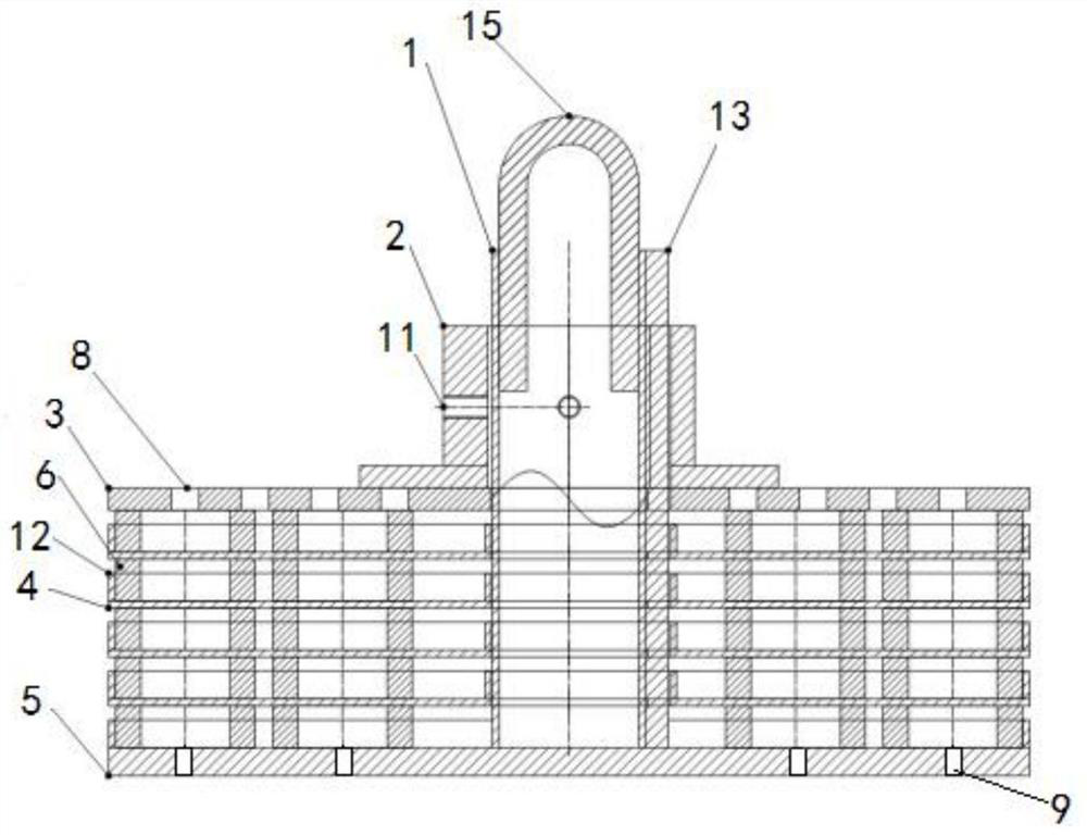
[0027] The purpose of the present invention is to provide a charging rack for common-mode iron core transverse magnetic treatment to solve the problems existing in the prior art, improve single furnace production, improve charging efficiency, reduce production costs, and prevent product damage.

[0028] In order to make the above objects, features and advantages of the present invention more comprehensible, the present invention will be further described in det...


PUM


Abstract

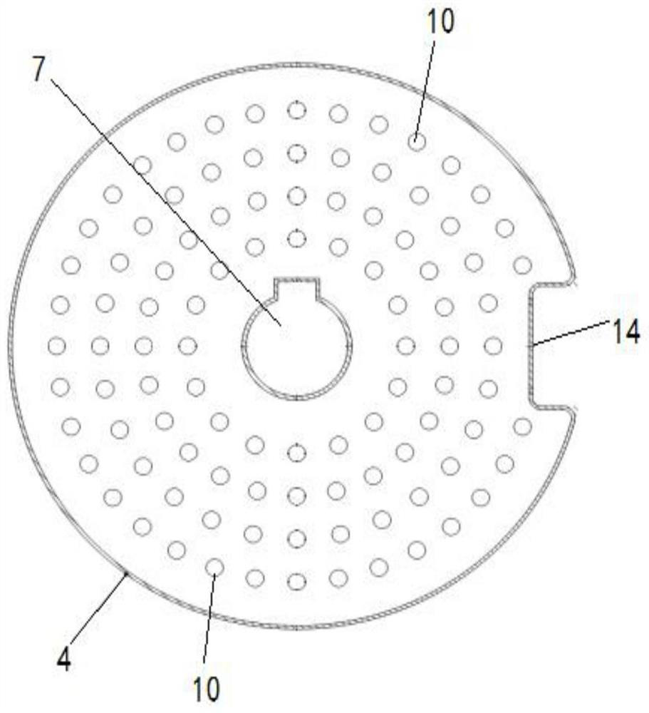
The invention discloses a furnace charging rack for transverse magnetic treatment of common-mode iron cores, and relates to the technical field of metal heat treatment. The furnace charging rack for transverse magnetic treatment of common-mode iron cores comprises a stand column, a tray locking device, a tray upper cover plate, a plurality of trays and a base, wherein the stand column is fixedly connected with the center of the base and is perpendicular to the base; a plurality of a first ventilation holes are formed in the base; a first through hole is formed in the center of each tray, eachtray is sequentially arranged on the stand column in a sleeving mode through the respective first through holes and stacked on the base, and each tray is provided with a plurality of second ventilation holes; the tray locking device is arranged on the stand column in a sleeving mode and can press each tray; and the tray upper cover plate is arranged between the tray locking device and the uppermost tray, and a cover plate radiating hole is formed in the tray upper cover plate. According to the furnace charging rack for transverse magnetic treatment of common-mode iron cores, the multiple traysare arranged for containing iron cores, and the ventilation holes are arranged, so that the heat is fully dissipated in the treatment process. The locking device is arranged to prevent iron cores from falling, the single-furnace production capacity is improved, the charging efficiency is improved, the production cost is reduced, and products can be prevented from being damaged.

Description

technical field [0001] The invention relates to the technical field of metal heat treatment, in particular to a charging rack for common-mode iron core transverse magnetic treatment. Background technique [0002] In the prior art, when the common-mode iron core is treated with transverse magnetic treatment, the furnace loading method of the vertical charging rack is usually adopted. There are many radial feeding pipes between the top plate and the bottom plate of the vertical charging rack. When loading, put a magnetic guide plate on each feeding pipe first, then put an iron core, then put a magnetic guide plate, and then put an iron core, and repeat the operation in this way to load the material. This operation will not only consume A lot of labor costs, the charging efficiency is also low, and because there is a certain space between the feeding pipes that cannot be effectively used, resulting in a reduction in the amount of single furnace charging, increasing production c...

Claims


Application Information

Patent Timeline
Patent Type & Authority Applications(China)
IPC IPC(8): C21D9/00H01F41/02
CPCC21D9/0025H01F41/0253Y02P10/20
Inventor 张朝文杨树发张平
Owner BEIJING YEKE MAGNETIC MATERIAL
Features
  • R&D
  • Intellectual Property
  • Life Sciences
  • Materials
  • Tech Scout
  • Unparalleled Data Quality
  • Higher Quality Content
  • 60% Fewer Hallucinations
Learn More