
Centrifugal pump water supply device

A water replenishment device and a centrifugal pump technology, which are applied to components, pumps, and pump controls of pumping devices used for elastic fluids, and can solve problems such as high civil construction costs, time-consuming and labor-consuming, and affecting the normal operation of the water supply system.

Inactive Publication Date: 2020-09-15
XUZHOU NORMAL UNIVERSITY
View PDF9 Cites 0 Cited by
  • Summary
  • Abstract
  • Description
  • Claims
  • Application Information

AI Technical Summary

Problems solved by technology

[0002] The water inlet of the centrifugal pump must be filled with water. Once there is no water in the water inlet of the centrifugal pump, the mechanical seal of the centrifugal pump will be broken due to the heat generated by high-speed rotation, which will affect the normal operation of the entire water supply system. Now the common solution One is to install a water filling cup at the front end of the centrifugal pump, and fill the pipeline with water before starting each time. This method is time-consuming and labor-intensive, and is extremely inconvenient. Another method is to install the centrifugal pump at the lowest water level of the reservoir Below, this method has many disadvantages. Firstly, it is necessary to build an underground or semi-underground pumping station, which occupies a large area and requires high civil construction costs. Secondly, the pumping station also needs to have moisture-proof and ventilation conditions. Therefore, a simple and reliable structure is required. Centrifugal pump water supply device

Method used


Image

  • Centrifugal pump water supply device
  • Centrifugal pump water supply device
  • Centrifugal pump water supply device

Examples


Embodiment

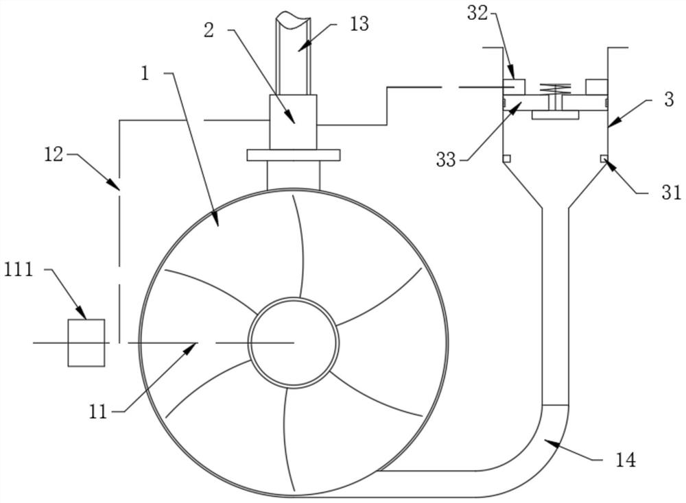
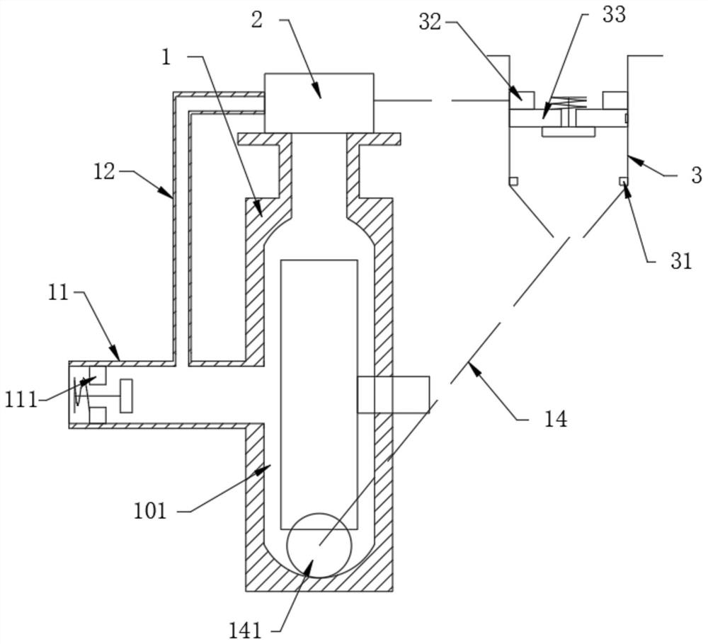
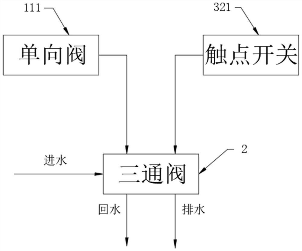
[0021] Such as figure 1 and figure 2 As shown, the centrifugal pump water supply device includes an impeller shell 1, an inlet pipe 11 is provided at the middle of the impeller shell 1, a three-way valve 2 is provided above the impeller shell 1, and a return pipe 12 and a return pipe 12 are connected to the output end of the three-way valve 2. The drain pipe 13 and the return pipe 12 are in communication with the water inlet pipe 11. The water inlet pipe 11 is provided with a one-way valve 111, and the one-way valve 111 is located at the front end of the return pipe 12. One side of the impeller shell 1 is provided with a water supply bucket 3, and a water supply bucket 3 The water supply pipe 14 communicates with the impeller cavity 101 in the impeller shell 1, and the inner wall of the water supply barrel 3 is provided with a lower limit stop ring 31 and an upper limit stop ring 32, the upper limit stop ring 32 is located above the lower limit stop ring 31, and the lower lim...


PUM


Abstract

The invention discloses a centrifugal pump water supply device. The centrifugal pump water supply device comprises an impeller shell, a water inlet pipe is arranged at the middle position of the impeller shell, a three-way valve is arranged above the impeller shell, the output end of the three-way valve is connected with a reflux pipe and a drainage pipe, the reflux pipe communicates with the water inlet pipe, a one-way valve is arranged in the water inlet pipe, the one-way valve is located at the front end of the reflux pipe, and a water supply barrel is arranged on one side of the impeller shell. The centrifugal pump water supply device is provided with the water supply barrel communicating with an impeller cavity, the water quantity in the water supply barrel is higher than the size ofthe impeller cavity to ensure the normal start of an impeller, when the impeller in the impeller cavity rotates, water can be dumped into the water supply barrel, and the next water supply can be guaranteed by using a float plate to storage water; and a contact switch is arranged in the water supply barrel, the drainage pipe is opened when water in the water supply barrel is greater than the amount to be supply next time, the function of automatic drainage is realized, and the sufficient water supply next time can further be ensured.

Description

technical field [0001] The invention relates to the technical field of water pumps, in particular to a centrifugal pump water supply device. Background technique [0002] The water inlet of the centrifugal pump must be filled with water. Once there is no water in the water inlet of the centrifugal pump, the mechanical seal of the centrifugal pump will be broken due to the heat generated by high-speed rotation, which will affect the normal operation of the entire water supply system. Now the common solution One is to install a water filling cup at the front end of the centrifugal pump, and fill the pipeline with water before starting each time. This method is time-consuming and labor-intensive, and is extremely inconvenient. Another method is to install the centrifugal pump at the lowest water level of the reservoir Below, this method has many disadvantages. Firstly, it is necessary to build an underground or semi-underground pumping station, which occupies a large area and r...

Claims


Application Information

Patent Timeline
Patent Type & Authority Applications(China)
IPC IPC(8): F04D9/00F04D29/42F04D15/00
CPCF04D9/00F04D15/0005F04D29/426
Inventor 徐丹
Owner XUZHOU NORMAL UNIVERSITY
Learn More