
Hydraulic oil tank actual working condition simulating device and hydraulic oil tank durability test method

A technology of hydraulic oil tank and actual working conditions, which is applied in the direction of oil supply tank device, fluid pressure actuating device, accumulator device, etc. and other problems, to achieve the effect of reducing test components and pipelines, ensuring consistency and accuracy, and simplifying the system

Active Publication Date: 2020-09-15
XCMG EXCAVATOR MACHINERY
View PDF2 Cites 1 Cited by
  • Summary
  • Abstract
  • Description
  • Claims
  • Application Information

AI Technical Summary

Problems solved by technology

[0002] At present, when the durability test of the hydraulic oil tank is carried out, the method of inflation simulation is used to increase the pressure in the oil tank, but because the gas is filled, it cannot reflect the change of the hydraulic oil volume in the oil tank when the hydraulic oil tank is actually working; and In this method, after the hydraulic oil tank is deflated, the minimum pressure in the oil tank is the normal atmospheric pressure, and it cannot simulate the actual working conditions, when the oil pump absorbs oil, the negative pressure in the oil tank is generated; nor can it simulate the pressure generated by the weight change of the hydraulic oil itself on the hydraulic oil tank influences

Method used


Image

  • Hydraulic oil tank actual working condition simulating device and hydraulic oil tank durability test method

Examples


Embodiment Construction

[0026] The present invention will be further described below in conjunction with the accompanying drawings. The following examples are only used to illustrate the technical solution of the present invention more clearly, but not to limit the protection scope of the present invention.

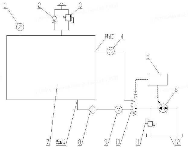
[0027] combine figure 1 As shown, the actual working condition simulation device of the hydraulic oil tank in this embodiment is mainly for simulating the actual working condition of the hydraulic oil tank and performing the durability test of sucking back oil.

[0028] The actual working condition simulation device of the hydraulic oil tank includes a controller 5 , a two-way variable pump 6 , a filter 8 , a reversing valve 10 , an overflow valve 11 , and an oil tank 12 .

[0029] The oil suction port of the hydraulic oil tank 7 to be tested is connected with the two-way variable pump 6 through the oil suction pipeline through the reversing valve 10 . The oil return port of the hydraulic oil ...


PUM


Abstract

The invention discloses a hydraulic oil tank actual working condition simulating device and a hydraulic oil tank durability test method. The hydraulic oil tank actual working condition simulating device comprises a bidirectional variable pump, a reversing valve and an oil tank; the bidirectional variable pump is correspondingly connected to an oil suction opening and an oil return opening of a hydraulic oil tank to be tested through the reversing valve; when the reversing valve is at the first position, the oil suction opening of the hydraulic oil tank to be tested communicates with the bidirectional variable pump, and the bidirectional variable pump sucks hydraulic oil from the hydraulic oil tank to be tested and is pumped into the oil tank through an oil suction pipeline; when the reversing valve is at the second position, the oil return opening of the hydraulic oil tank to be tested communicates with the bidirectional variable pump, and the bidirectional variable pump sucks the hydraulic oil from the oil tank and is pumped into the hydraulic oil tank to be tested through an oil return pipeline. Through the suction and return of the hydraulic oil, the volume change of the hydraulic oil in the hydraulic oil tank is simulated, meanwhile, the influence of the weight of the hydraulic oil on the oil tank is considered, the negative pressure condition in the oil tank is further simulated, the negative pressure condition is closer to the actual condition of the hydraulic oil tank, and the testing accuracy is ensured. The system is simple, and the testing cost is reduced.

Description

technical field [0001] The invention relates to a hydraulic oil tank actual working condition simulation device and a hydraulic oil tank durability test method, belonging to the technical field of hydraulic oil tank testing. Background technique [0002] At present, when the durability test of the hydraulic oil tank is carried out, the method of inflation simulation is used to increase the pressure in the oil tank, but because the gas is filled, it cannot reflect the change of the hydraulic oil volume in the oil tank during the actual working condition of the hydraulic oil tank; and In this method, after the hydraulic oil tank is deflated, the minimum pressure in the oil tank is the normal atmospheric pressure, which cannot simulate the actual working conditions, when the oil pump absorbs oil, and the negative pressure in the oil tank is generated; nor can it simulate the pressure generated by the weight change of the hydraulic oil itself on the hydraulic oil tank influences...

Claims


Application Information

Patent Timeline
IPC IPC(8): F15B19/00F15B1/26
CPCF15B19/00F15B19/007F15B1/265
Inventor 王修通肖云博曹西朴巩亚飞张昆秦强
Owner XCMG EXCAVATOR MACHINERY
Learn More