Two-dimensional bar code laser marking method

A technology of laser marking and dimensional bar code, which can be applied in temperature recording method, digital marking record carrier, digital marking by photographing/thermal imaging, etc., which can solve the problems of reducing and wasting time.

Inactive Publication Date: 2003-07-30
MIYACHI TECHNOS CORP
View PDF4 Cites 0 Cited by
  • Summary
  • Abstract
  • Description
  • Claims
  • Application Information

AI Technical Summary

Problems solved by technology

[0015] Furthermore, to avoid degradation of the marking quality at the opposite end of the barcode, as Figure 17 As shown, the co

Method used


Image

  • Two-dimensional bar code laser marking method
  • Two-dimensional bar code laser marking method
  • Two-dimensional bar code laser marking method

Examples


Embodiment Construction

[0039] Below in conjunction with represented the preferred embodiment of the present invention Figure 1 to Figure 13 The invention is described.

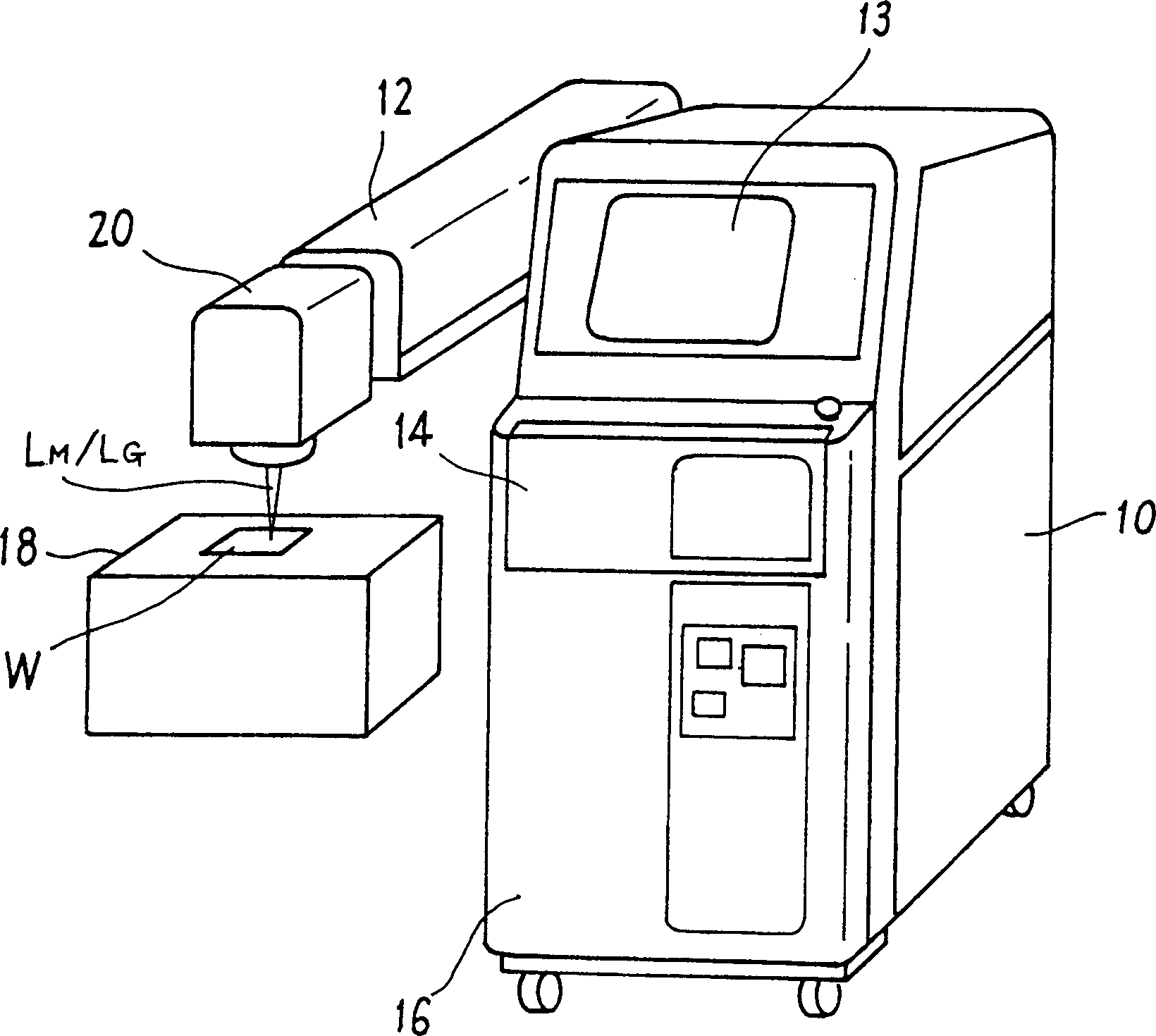
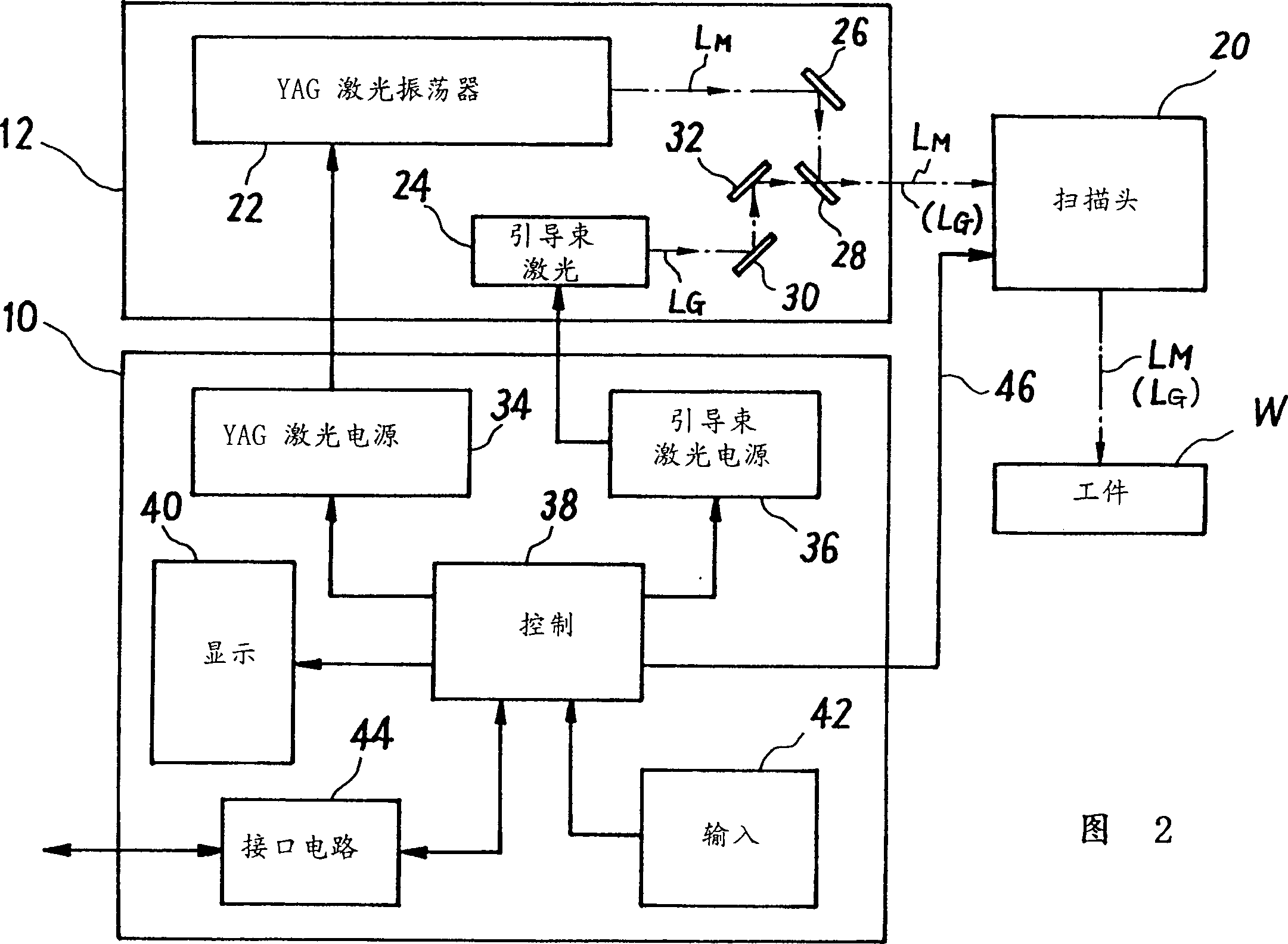
[0040] figure 1 A scanning type YAG (yttrium aluminum garnet) laser marking device used in a laser marking method according to an embodiment of the present invention is shown. The YAG laser marking device includes a control power supply unit 10 , a laser oscillation unit 12 and a scanning head 20 .

[0041] The control power supply unit 10 includes an upper member provided with a display 13 composed of a display unit, a middle member provided with a keyboard and a control panel (the back of the front door 14), and a laser power supply circuit, a laser cooling device, etc. etc. lower member (the back of the front door 16). The scan control signal is generated by the control unit within the intermediate member and transmitted to the scan head 20 through a predetermined signal line (not shown). The scanning head 20 is placed at t...


PUM


Abstract

In marking execution mode, after initialization, a scanning control signal based on predetermined marking data and condition data is sent to a scanning head (20) so that a beam spot of a YAG laser beam scans spirally on the interior of a predetermined first black cell (CEB) in a two-dimensional bar code marking region on the surface of a workpiece (W). After the completion of the spiral scanning on the interior of the first black cell, the beam spot skips over from the scanning end point to a scanning start point of a second black cell (CEB) adjacent to that end point. Then, the interior of the second black cell is also scanned with the beam spot in a unit plotting pattern similar to the above. Afterward, the same spiral scanning as the above is iteratively made on a third and all subsequent black cells (CEB). Upon the completion of the spiral scanning on the last black cell, all the marking actions are complete.

Description

technical field [0001] The invention relates to a laser marking method for establishing a matrix type two-dimensional barcode. Background technique [0002] Recently, signatures using two-dimensional barcodes with two-dimensional orientation information have become popular. The two-dimensional barcode includes a stacked barcode composed of a one-dimensional barcode with vertical stacking to display information using its vertical and horizontal representations, and black and white cells arranged in a mosaic manner (matrix type) in the vertical and horizontal directions A matrix-type barcode composed and used to display information. [0003] Figure 14 Data codes are shown as a general standard for matrix types. [0004] The data code includes L-shaped leading cells or edge cells consisting of black cells arranged consecutively in an L; timing cells consisting of black and white cells alternately arranged opposite to said edge cells; A data area composed of black and white ...

Claims


Application Information

Patent Timeline
IPC IPC(8): B41M5/26G06K1/12
CPCG06K15/029G06K1/126B41M5/26B41M5/24G06K19/06037
Inventor 许丰余
Owner MIYACHI TECHNOS CORP
Why Eureka
Try Eureka