Temperature control method and system

A temperature control method and technology of temperature control system, applied in temperature control, control/regulation system, non-electric variable control and other directions, can solve the problems of temperature shock, poor overshoot performance, relatively large temperature fluctuation, etc. Strong, accurate control and controllable effects

Active Publication Date: 2020-09-15
BEIJING NAURA MICROELECTRONICS EQUIP CO LTD
View PDF12 Cites 3 Cited by
  • Summary
  • Abstract
  • Description
  • Claims
  • Application Information

AI Technical Summary

Problems solved by technology

[0005] 1. At present, most of the control links in the temperature controller adopt PID (Proportional Integral Derivative, proportional integral derivative) control. Although the theoretical basis of PID control is sufficient, the response speed of PID control itself is not good enough, resulting in the overshoot of its control. Relatively poor performance, there will be a short-term temperature shock under high-temperature use, and the temperature fluctuation is relatively large
[0006] 2. The main engine outputs the set temperature to the temperature controller. The specific control depends on the parameter setting of the temperature controller itself. The change of the control strategy needs to readjust the parameters of the temperature controller, and the change of the PID parameter has a certain influence on the control result. Unpredictability, so the client's autonomous intelligence is relatively poor

Method used


Image

  • Temperature control method and system
  • Temperature control method and system
  • Temperature control method and system

Examples


Embodiment 1

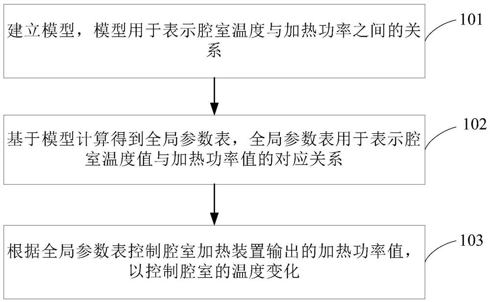
[0050] Such as figure 2 Shown is a flow chart of the temperature control method provided by the embodiment of the present invention, including the following steps:

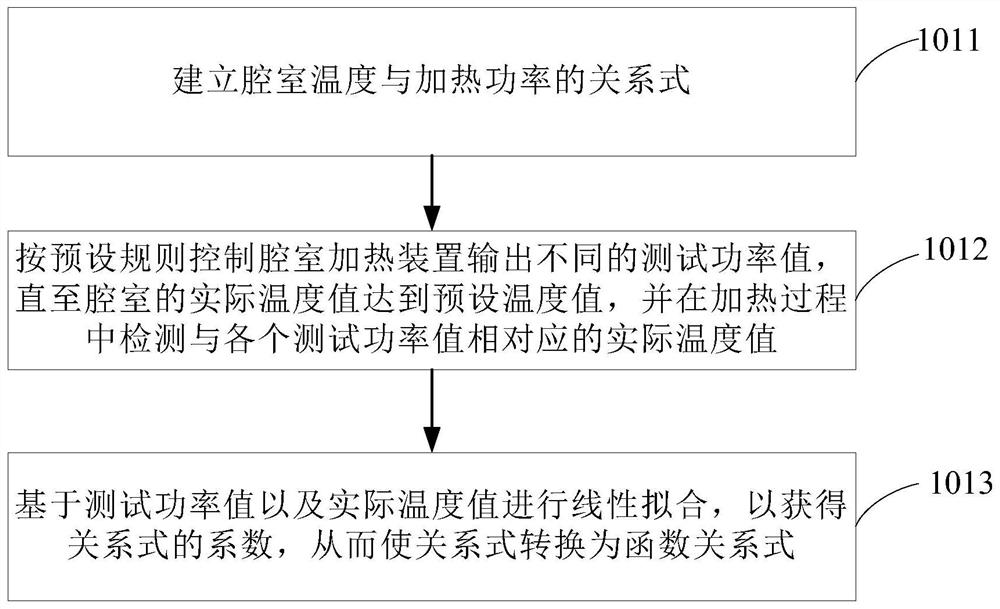
[0051] Step 101: Establish a model, the model is used to represent the relationship between the chamber temperature and the heating power.

[0052] Specifically, the model building step: control the chamber heating device to output different test power values ​​to the chamber, obtain the actual temperature value of the chamber corresponding to each test power value, and according to the relationship between the actual temperature value and the test power value Modeling.

[0053] Specifically, both the test power value and the heating power are the output power of the chamber heating device, and the test power value is only the heating power of the chamber heating device during the test process, and the output power of the chamber heating device.

[0054] Step 102: Calculate and obtain a global parameter table b...

Embodiment 2

[0073] Such as Figure 6 Shown is another flow chart of the temperature control method provided by the embodiment of the present invention, including the following steps:

[0074] Step 201: Establish a model, which is used to represent the relationship between the chamber temperature and heating power.

[0075] Step 202: Calculate and obtain a global parameter table based on the model, and the global parameter table is used to represent the corresponding relationship between the chamber temperature value and the heating power value.

[0076] Step 203: Control the heating power value output by the chamber heating device according to the global parameter table, so as to control the temperature change of the chamber.

[0077] Step 204: Obtain the actual value of the chamber temperature and the actual value of the heating power within the set period.

[0078] Specifically, the set period may be determined according to process requirements, for example, the set period is 1 h.

...

Embodiment 3

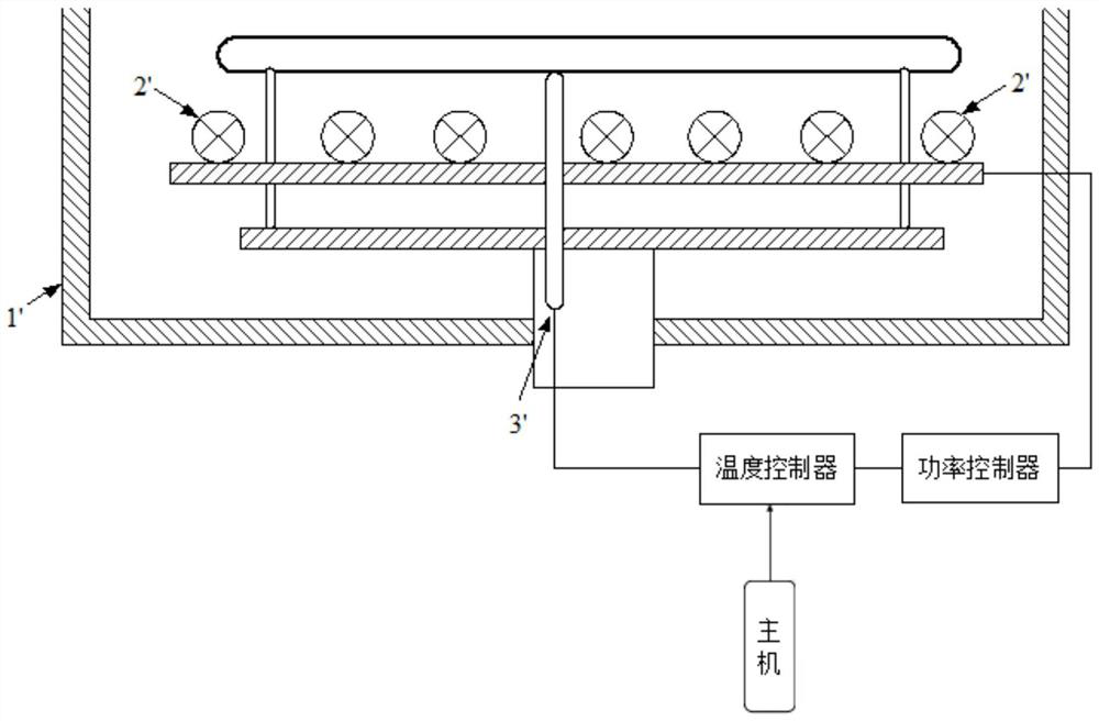
[0086] For the above temperature control method, the present invention also provides a temperature control system, such as Figure 7 As shown, the temperature control system includes: a chamber heating device. The system also includes: upper computer and lower computer;

[0087] The upper computer is used to control the chamber heating device to output different test power values ​​to the chamber, and obtain the actual temperature value of the chamber corresponding to each test power value; establish a model based on the relationship between the actual temperature value and the test power value, A model is used to represent the relationship between chamber temperature and heating power. The upper computer is also used to calculate the global parameter table based on the model, and output control signals to the lower computer according to the global parameter table; the global parameter table is used to represent the corresponding relationship between the chamber temperature v...


PUM


Abstract

The invention provides a temperature control method and system and semiconductor equipment. The temperature control method is used for controlling the temperature change of a chamber. The method comprises the following steps: establishing a model: controlling a chamber heating device to output different test power values to the chamber, obtaining actual temperature values, corresponding to the test power values, of the chamber, and establishing a model according to the relationship between the actual temperature values and the test power values, wherein the model is used for representing the relationship between the chamber temperature and the heating power; calculating a global parameter table based on the model, wherein the global parameter table is used for representing a correspondingrelationship between the chamber temperature value and the heating power value; and controlling the heating power value output by the chamber heating device according to the global parameter table soas to control the temperature change of the chamber. According to the invention, the temperature of the chamber is flexibly and accurately controlled.

Description

technical field [0001] The present invention relates to the field of semiconductor manufacturing, in particular to a temperature control method and system. Background technique [0002] At present, the temperature control system has an important impact on the consistency of film deposition quality during the PVD (Physical Vapor Deposition, physical vapor deposition) process, and the fluctuation and inaccuracy of the chamber temperature will inevitably greatly reduce the process results of the wafer. [0003] Specifically, the block diagram of the temperature control system is shown as figure 1 as shown, figure 1 In the chamber 1', each heater 2' is grouped by area, and the heaters 2' in the same group are controlled by the same power controller. The temperature measurement adopts the contact thermocouple measurement method, the thermocouple 3' measures the temperature and sends the measurement result to the temperature controller, the temperature controller generates a con...

Claims


Application Information

Patent Timeline
Patent Type & Authority Applications(China)
IPC IPC(8): G05D23/22
CPCG05D23/22
Inventor 梁彦
Owner BEIJING NAURA MICROELECTRONICS EQUIP CO LTD
Why Eureka
Try Eureka