Enameled skin removing device for flat copper wire

A flat copper wire and mounting seat technology, applied in the direction of electromechanical devices, cable installation devices, cable installation, etc., can solve problems such as increased repair welding, affecting the welding quality of 192 welding spots of high-efficiency generator stators, and affecting the power generation performance of motors

Pending Publication Date: 2020-09-15
成都华川电装有限责任公司
View PDF0 Cites 2 Cited by
  • Summary
  • Abstract
  • Description
  • Claims
  • Application Information

AI Technical Summary

Problems solved by technology

The existing flat copper wire stripping process is provided with two stations, which are the horizontal cutter stripping station and the longitudinal stripping stripping station. This method has a big problem. , the four sides of the flat copper wire can only be cut off at two stations, but the paint skin on the four edges is still not removed, which seriously affects the welding quality of the 192 solder joints of the high-efficiency generator stator, and will also lead to more repair welding. It has seriously affected the production efficiency. If the paint skin on the four edges is to be removed by cutting horizontally and vertically, the integrity of the flat copper wire substrate will not be guaranteed, which will eventually affect the power generation performance of the motor; if you want to add a third The station specially removes the paint on the four edges, which increases the cost and reduces the production efficiency

Method used


Image

  • Enameled skin removing device for flat copper wire
  • Enameled skin removing device for flat copper wire
  • Enameled skin removing device for flat copper wire

Examples


Embodiment Construction

[0026] A kind of embodiment of flat copper wire stripping device of the present invention:

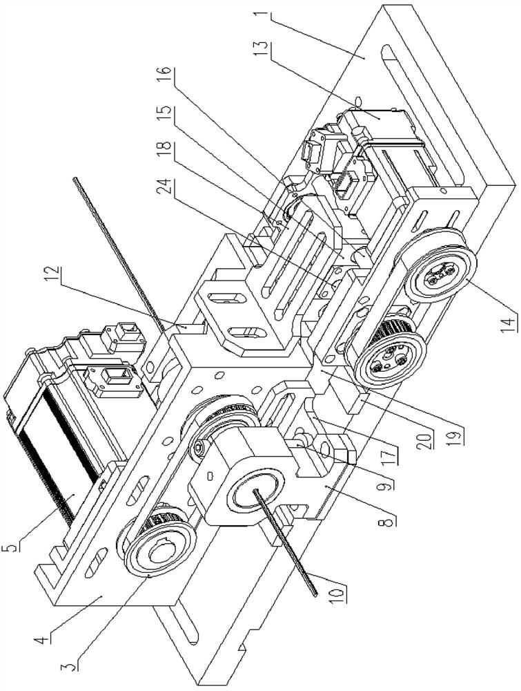
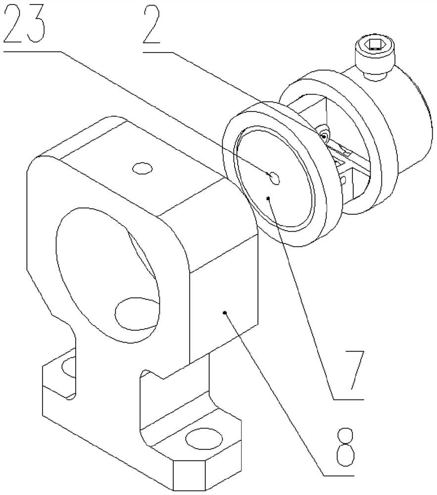
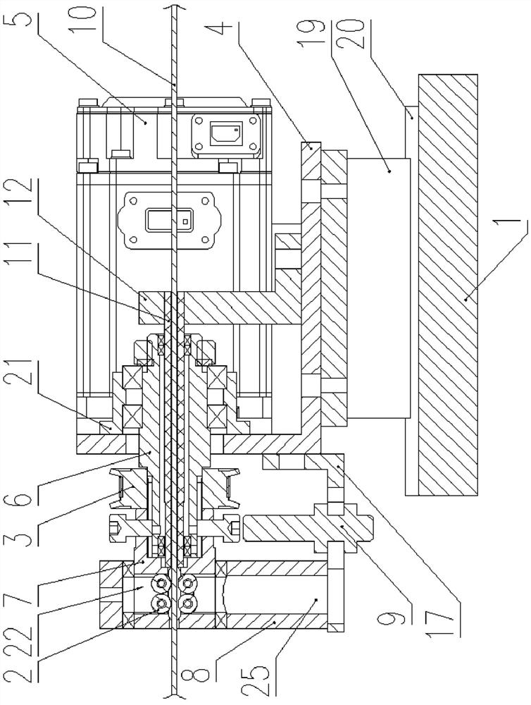
[0027] see Figure 1-Figure 4, a flat copper wire paint remover, comprising a base plate 1, a paint remover is slidably fitted on the base plate 1, and a displacement drive device is fixedly installed, and the paint remover includes a mounting seat 4, a second motor 5, a second Pulley transmission mechanism 3, hollow rotating shaft 6, cutter body 7, cutter body support seat 8, a bearing seat 21 is installed by screw on the described mounting seat 4, and described hollow rotating shaft 6 is supported in this bearing seat 21 by bearing, makes The hollow shaft 6 can rotate in the bearing housing 21 . One end of the hollow rotating shaft 6 extends out of the mounting base 4 and is connected with the rotating shaft of the second motor 5 installed on the mounting base 4 through the second pulley transmission mechanism 3 , and the driven wheel circumference of the hollow rotating shaft 6 and...


PUM


Abstract

The invention discloses an enameled skin removing device for a flat copper wire. The device comprises a bottom plate. A paint removing device is in sliding fit with the bottom plate. A displacement driving device is fixedly mounted. The paint removing device comprises a mounting base, a second motor, a second belt wheel transmission mechanism, a hollow rotating shaft, a cutter body and a cutter body supporting base. The hollow rotating shaft is supported on the mounting base. The hollow rotating shaft is connected with a rotating shaft of a second motor through a second belt wheel transmissionmechanism. One end of the cutter body is connected with the hollow rotating shaft, the other end of the cutter body is in sliding fit with the cutter body supporting seat through a bearing, an origindetection device corresponds to the cutter body, a cutter mounting cavity and a wire passing hole are formed in the cutter body, a paint removing cutter is arranged in the cutter mounting cavity, anda wire passing pipe is in sliding fit in a shaft hole of the hollow rotating shaft. The displacement driving device comprises a first motor, a first belt wheel transmission mechanism, a screw rod mechanism and a screw rod mechanism. The first motor is fixed on the bottom plate, the screw rod mechanism is connected with the first motor through the first belt wheel transmission mechanism, the screwrod mechanism comprises a sliding block in threaded fit with a screw rod, and the sliding block is fixedly connected with the mounting seat.

Description

technical field [0001] The invention relates to the technical field of paint removal, in particular to a paint removal device for flat copper wires. Background technique [0002] The outer surface of the copper wire is usually coated with varnish to insulate and protect the inner pure copper wire. In the subsequent use of the copper wire, the outer protective layer of the copper wire needs to be peeled off. Taking the 96-slot high-efficiency generator stator winding as an example, each slot has four flat copper wires, and the two adjacent flat copper wires are welded together. Each slot forms two solder joints, and each flat copper wire needs to be The paint on the copper wire head is removed cleanly, and the base material of the flat copper wire must be intact to ensure the quality of the 192 solder joints in the 96 slots of the high-efficiency generator stator and the one-time qualified rate of welding. The existing flat copper wire stripping process is provided with two ...

Claims


Application Information

Patent Timeline
Patent Type & Authority Applications(China)
IPC IPC(8): H02G1/12H02K15/00H01R43/02
CPCH01R43/02H02G1/1265H02K15/0068
Inventor 陈宗海张小兵
Owner 成都华川电装有限责任公司
Why Eureka
Try Eureka