A portable high frequency inverter power supply
A high-frequency inverter and portable technology, which is applied in the direction of electrical components, conversion equipment structural parts, electrical equipment shells/cabinets/drawers, etc. Inconvenience and other problems, to achieve the effect of improving portability, preventing short circuit, and saving labor in the lifting process
- Summary
- Abstract
- Description
- Claims
- Application Information
AI Technical Summary
Problems solved by technology
Method used
Image
Examples
Embodiment 1
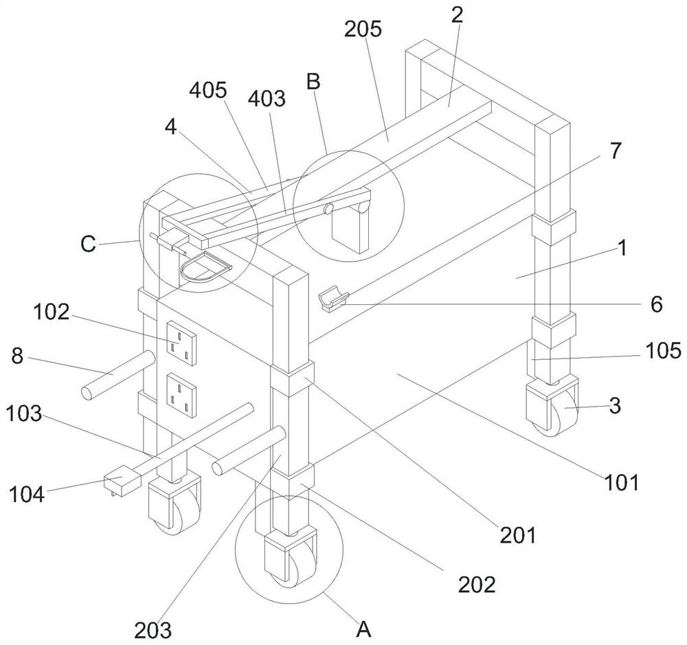
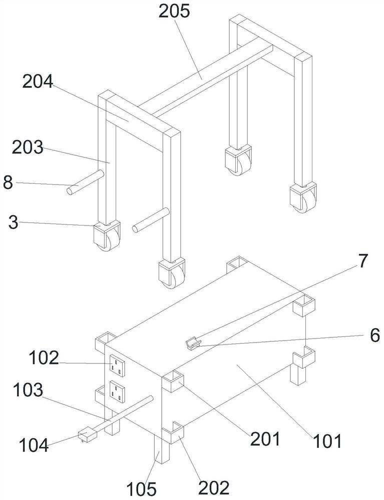
[0027] Refer Figure 1 - Figure 5 A portable high-frequency inverter power supply includes a high frequency inverter power source 1. The high frequency inverter power source 1 includes a power housing 101, and the left side of the power housing 101 fixedly connected to the power supply output socket 102, the power housing 101 The front end of the left side is fixedly connected to the power input line 103. The left side surface of the power input line 103 is fixedly connected to the power input plug 104, and the lower surface of the power housing 101 is fixedly connected to the support leg 105;
[0028] The upper end of the power housing 101 is provided with a portable mobile device 2;
[0029] A rolling device 3 is provided below the portable mobile device 2;
[0030] The upper end of the portable mobile device 2 is provided with a transmission 4;
[0031] The front end of the portable mobile device 2 is provided with a transmission fixture 5.
[0032] In use, the power input plug ...
Embodiment 2
[0034] Refer Figure 1 - Figure 2 A portable high-frequency inverter power source is basically the same as that, further, in the portable mobile device 2, the portable mobile device 2 includes a fixed tube one 201 and a fixed tube 2 202, a fixed tube one 201 and a fixed tube two The rear side surface of 202 is fixed to the front side surface of the power housing 101, the inner wall of the fixed tube one 201 and the fixed tube 2 202 is slidable to be slidably connected to the support column 203, and the upper end of the support post 203 is fixed to the upper side of the support crossbar 124, and the support is horizontal. The right side of the rod 124 is fixedly connected to the support crossbar 2 205.
[0035] In use, the support post 203 slides to connect the fixed tube one 201 and the fixed tube 2 202, and the support of the support column 203 on the front and rear sides of the front and rear sides, support the cross-rod 2 205, and support the support cross-rod 124, so that The p...
Embodiment 3
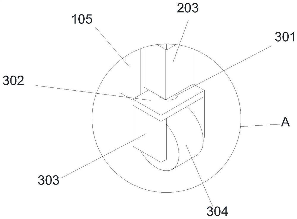
[0037] Refer Figure 1 - Figure 3A portable high-frequency inverter power source is substantially the same as in Example 1, and further, the rolling apparatus 3 includes a support shaft 301, and the upper surface of the support shaft 301 is fixedly coupled to the lower surface of the support post 203, The lower surface of the support shaft 301 is rotated by the bearing, and the support plate 303 is fixed to the left and right ends of the support plate 302, and the inner side surface of the support side panel 303 is rotated by the rotating shaft and the bearing. 304.
[0038] When the support post 203 is slid down to disengage the upper surface of the support leg 105, the rolling device 3 is responsible for the load weight of the entire device. At this time, the lower surface of the roller 304 contacts the ground, the support shaft 301 causes the support plate 302, the support side. The plate 303 and the roller 304 can be rotated relative to the support post 203 to facilitate adjust...
PUM
 Abstract
Description
Claims
Application Information
 - R&D
- Intellectual Property
- Life Sciences
- Materials
- Tech Scout
- Unparalleled Data Quality
- Higher Quality Content
- 60% Fewer Hallucinations
Browse by: Latest US Patents, China's latest patents, Technical Efficacy Thesaurus, Application Domain, Technology Topic, Popular Technical Reports.
© 2025 PatSnap. All rights reserved.Legal|Privacy policy|Modern Slavery Act Transparency Statement|Sitemap|About US| Contact US: help@patsnap.com


