Antenna switching method, device, terminal and storage medium
An antenna switching and storage medium technology, applied in diversity/multi-antenna systems, radio transmission systems, advanced technologies, etc., can solve the problems of low integration, larger hardware channel layout area, and increased manufacturing cost, and reduce the layout area. , Simplify the complexity of hardware design and improve the effect of integration
- Summary
- Abstract
- Description
- Claims
- Application Information
AI Technical Summary
Problems solved by technology
Method used
Image
Examples
Embodiment 1
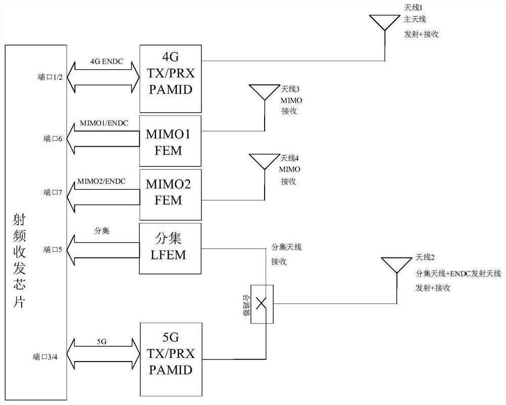
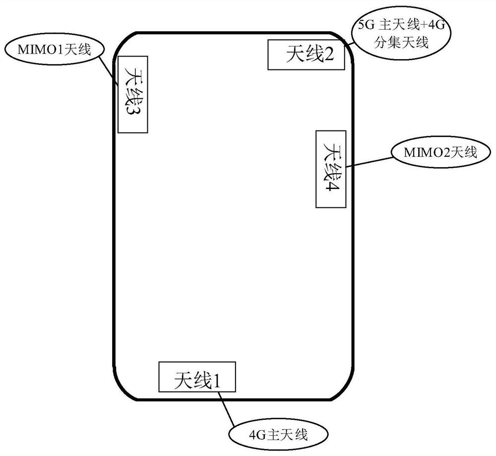
[0073] Please see attached Figure 5 , is a schematic flowchart of an antenna switching method provided in Embodiment 1 of the present invention. The method is suitable for a scenario where a 5G NR terminal in an NSA network performs antenna switching. In this scenario, the hardware path of the radio frequency front end performs and figure 2 The same antenna is combined, which greatly simplifies the hardware path. And the antenna layout for the image 3 Same. The method is performed by an antenna switching device, which can be implemented by software and / or hardware, and is integrated inside the terminal. The method specifically includes the following steps:
[0074] S101. Detect whether the terminal is in a handheld state; if the terminal is in a handheld state, proceed to step S102, and if the terminal is not in a handheld state, continue to perform step S101.
[0075] It should be noted that the present invention determines whether the terminal is currently in a handhe...
Embodiment 2
[0096] like Figure 7 As shown, the antenna switching method provided by the second embodiment of the present invention is based on the technical solution provided by the first embodiment, and further optimizes step S102 "detecting whether the first antenna working in the first network is interfered by hand-held." The explanations of terms that are the same as or corresponding to the above embodiments are not repeated here. which is:
[0097] Detecting whether signal attenuation occurs in the first antenna working on the first network;
[0098] When the signal attenuation of the first antenna occurs, calculate the signal attenuation of the first antenna;
[0099] Determine whether the signal attenuation is greater than or equal to a first threshold;
[0100] When the signal attenuation amount is greater than or equal to the first threshold, determining that the first antenna suffers from hand-held interference;
[0101] When the signal attenuation amount is less than the f...
Embodiment 3
[0113] Figure 8 This is a schematic flowchart of an antenna switching method provided by Embodiment 3 of the present invention. On the basis of Embodiment 1, this embodiment optimizes the method after step S103. The explanations of terms that are the same as or corresponding to the above embodiments will not be repeated here. For details, please refer to Figure 8 , the method includes:
[0114] S301. Detect whether the terminal is in a handheld state; if the terminal is in a handheld state, proceed to step S302, and if the terminal is not in a handheld state, continue to perform step S301.
[0115] S302. Detect whether the first antenna working in the first network is interfered by hand-held; if the first antenna is interfered by hand-held, go to step S303; if the first antenna is not interfered by hand-held, return to step S301 .
[0116] S303. Control the port of the second antenna working on the second network to call the code of the first network, and control the port...
PUM
 Abstract
Description
Claims
Application Information
 - R&D
- Intellectual Property
- Life Sciences
- Materials
- Tech Scout
- Unparalleled Data Quality
- Higher Quality Content
- 60% Fewer Hallucinations
Browse by: Latest US Patents, China's latest patents, Technical Efficacy Thesaurus, Application Domain, Technology Topic, Popular Technical Reports.
© 2025 PatSnap. All rights reserved.Legal|Privacy policy|Modern Slavery Act Transparency Statement|Sitemap|About US| Contact US: help@patsnap.com


