High-viscosity polymer polycondensation reactor based on combined stirring mechanism

A polycondensation reactor and stirring mechanism technology, applied in chemical/physical/physicochemical fixed reactors, mixers with rotating stirring devices, mixers, etc., can solve the problem of prolonged residence time, long production process, polymer Viscosity can not be further improved to achieve the effect of increasing the surface renewal rate and reducing the adhesion film

Active Publication Date: 2020-09-18
ZHEJIANG HENGYI PETROCHEMICAL RES INST CO LTD
View PDF4 Cites 1 Cited by
  • Summary
  • Abstract
  • Description
  • Claims
  • Application Information

AI Technical Summary

Problems solved by technology

On the other hand, when the polymer liquid film and the annular disc form a whole to rotate together, the flow of the subsequent polymer is blocked, and the surface renewal and polymerization reaction of the subsequent polymer are also restricted, so that the viscosity of the subsequent polymer cannot be further increased.
Therefore, when using the traditional disc reactor to produce polymers with higher viscosity, we can only add another set of viscosifying reactors, which makes the production process longer, and the residence time of the polymer at high temperature is prolonged, which affects the quality of the final product. quality, increased investment costs and production costs

Method used


Image

  • High-viscosity polymer polycondensation reactor based on combined stirring mechanism
  • High-viscosity polymer polycondensation reactor based on combined stirring mechanism
  • High-viscosity polymer polycondensation reactor based on combined stirring mechanism

Examples


Embodiment 1

[0074] Example 1 (ring disk stirrer + spiral blade stirrer)

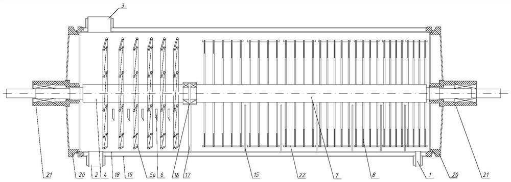
[0075] like figure 1 As shown, a high-viscosity polymer polycondensation reactor includes a horizontal cylindrical shell and a combined stirring mechanism arranged in the horizontal cylindrical shell. The bottom ends of the horizontal cylindrical shell are respectively provided with feeding materials. Port 1 and discharge port 2, the horizontal cylindrical shell is also provided with a gas phase port 3 on the side of the discharge port. The horizontal cylindrical shell includes an inner cylinder 18, a jacket body 19 (which can be heated by a heat medium) arranged on the outside of the inner cylinder, and end caps 20 arranged at both ends of the inner cylinder and the jacket jacket; The end cover is provided with a rotating shaft sleeve 21 for sealing and supporting the rotating shaft. The cross section of the inner cylinder is circular, and the centerline of the combined stirring mechanism is lower than the center...

Embodiment 2

[0081] Example 2 (cage frame type mesh disk stirrer + spiral blade type tube disk stirrer)

[0082] The difference between this embodiment and Embodiment 1 is:

[0083] The cross section of the inner cylinder is in the shape formed by connecting the upper and lower sides of the rectangle with a semicircle of the same radius, and the centerline of the combined stirring mechanism is concentric with the centerline of the lower semicircle in the cross section of the inner cylinder.

[0084] like Figure 5-6 As shown, the first agitator is a cage-type mesh disc agitator, including two circular flower plates 10, several strips 11, several mesh discs 12, inner short shafts 13 and outer short shafts 14; the strips Parallel to the axial direction of the horizontal cylindrical shell, the two circular flower plates are respectively vertically fixed to the two ends of the strips, and the mesh disks are vertically fixed to the axial direction of the strips in series. The plate, the slats...

Embodiment 3

[0086] Example 3 (ring disk stirrer + spiral ring tube stirrer)

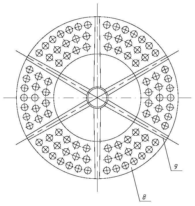
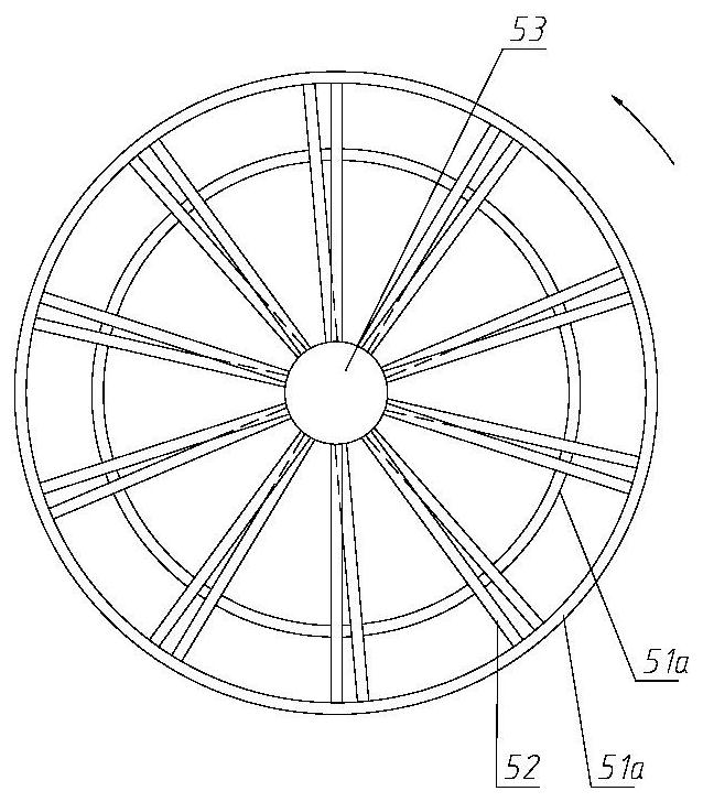
[0087] The difference between this embodiment and Embodiment 1 is that the second stirrer adopts a spiral ring tube stirrer. like Figure 7-9 As shown, the spiral ring tube agitator includes a second shaft 4 and a spiral ring tube 5b axially fixed to the second shaft; the spiral ring tube is projected along the axial direction of the second shaft by several axial projections with different diameters and lengths. The two ends of the second rotating shaft are respectively supported by the rotating shaft sleeve 21 fixed on the discharge side end cover 20 of the cylindrical shell and the sliding bearing seat 16 inside the cylinder. A shaft sleeve 53 is provided on the second rotating shaft, and the spiral ring is fixed on the shaft sleeve through a plurality of support bars 52 . The length of the helical ring with a larger diameter is greater than that of the helical ring with a smaller diameter, and the number of...


PUM


Abstract

The invention relates to the field of polymer production equipment, and discloses a high-viscosity polymer polycondensation reactor based on a combined stirring mechanism. The high-viscosity polymer polycondensation reactor comprises a horizontal cylindrical shell and a built-in combined stirring mechanism. The combined stirring mechanism comprises a first stirrer and a second stirrer, which are transversely connected in series and can independently rotate; wherein the first stirrer and the second stirrer are respectively close to the feed port and the discharge port. The first stirrer is an annular disc stirrer or a cage frame type net disc stirrer, and the second stirrer is a spiral blade type pipe disc stirrer or a spiral annular pipe stirrer. Two stirrers with different rotating speedsand different structures are arranged in the same reactor; a liquid film can still be efficiently updated when the viscosity of the polymer is higher, the mixing and mass transfer effects during highviscosity are effectively improved, the intrinsic viscosity of the polymer at the outlet of the reactor can be effectively improved, and the production capacity and the product range of the polycondensation reactor are effectively improved.

Description

technical field [0001] The invention relates to the field of polymer production equipment, in particular to a high-viscosity polymer polycondensation reactor based on a combined stirring mechanism. Background technique [0002] The current production and preparation of polytrimethylene terephthalate (PTT), polyethylene terephthalate (PET), polybutylene terephthalate (PBT), butylene adipate terephthalate Among the polycondensation reactors of alcohol ester (PBAT), polybutylene succinate (PBS) and other types of polyesters, the final polycondensation reactor is the key equipment in the entire production line and is the final polycondensation reactor for polyester polymerization. Disc reactors and cage frame reactors are widely used now. The viscosity of most of the existing reactors after polycondensation can reach 0.62~0.7dl / g. With the continuous development of new products, the viscosity of the material after polycondensation in the reactor is required to reach 0.95 dl / g ...

Claims


Application Information

Patent Timeline
Patent Type & Authority Applications(China)
IPC IPC(8): B01J19/18B01J19/00B01F7/00B01F7/02
CPCB01J19/18B01J19/0066B01F27/192B01F27/60B01F2101/2805
Inventor 贾振宇彭华锋张保勇柳铭轩陈文
Owner ZHEJIANG HENGYI PETROCHEMICAL RES INST CO LTD
Why Eureka
Try Eureka