Automatic compression packaging equipment for pop cans

A pop-up can, automatic technology, applied in the direction of press, mobile filter element filter, separation method, etc., can solve the problems of inconvenient operation, low work efficiency, laborious, etc., to achieve convenient operation, high work efficiency, and avoid offset. Effect

Active Publication Date: 2022-06-17
NANJING HANXIYUE AUTOMATION TECH CO LTD
View PDF12 Cites 0 Cited by
  • Summary
  • Abstract
  • Description
  • Claims
  • Application Information

AI Technical Summary

Problems solved by technology

[0004] In order to overcome the disadvantages that people need to manually compress the cans, which takes a long time and is laborious, and requires constant replacement of the cans for compression, which is inconvenient to operate and leads to low work efficiency. The technical problem of the present invention is to provide a Compression is relatively labor-saving, and can continuously compress cans, easy to operate, high-efficiency automatic compression packaging equipment for cans

Method used


Image

  • Automatic compression packaging equipment for pop cans
  • Automatic compression packaging equipment for pop cans
  • Automatic compression packaging equipment for pop cans

Examples


Embodiment 1

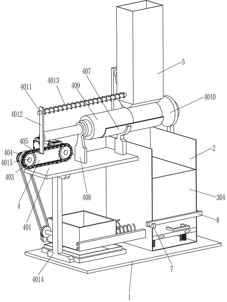
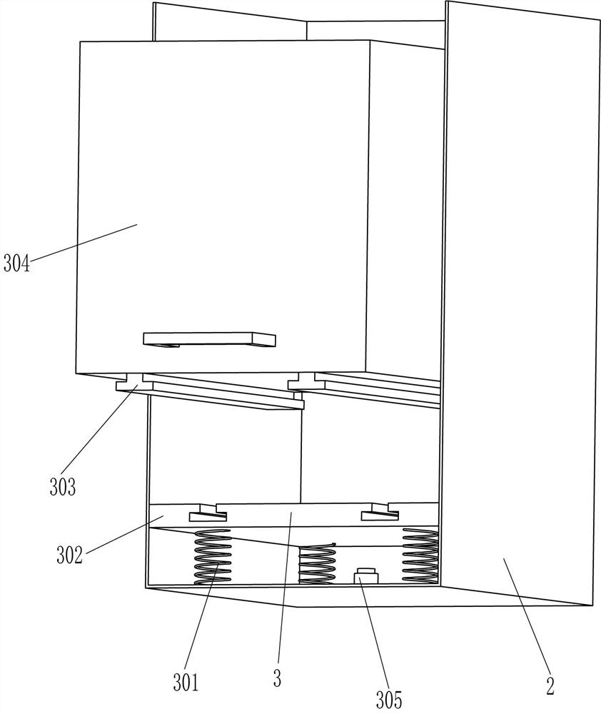
[0020] see Figure 1-Figure 3 , an automatic compression and packaging equipment for cans, including a bottom plate 1, a shell 2, a collection mechanism 3, a compression mechanism 4, a placing cylinder 5, a fixed seat 6, a stopper 7 and a swing rod 8. The top right side of the bottom plate 1 is fixed with a Housing 2, a collection mechanism 3 is arranged in the housing 2, a fixed seat 6 is fixedly connected to the front side of the lower part of the outer right side of the housing 2, and a swing rod 8 is rotatably connected to the fixed seat 6, and the swing rod 8 is connected with the collection mechanism 3 Matching, a stopper 7 is fixed on the front side of the lower part of the outer left side of the housing 2, and the stopper 7 is in contact with the swing rod 8. A compression mechanism 4 is arranged between the top left side of the bottom plate 1 and the outer upper part of the housing 2. A placing cylinder 5 is fixed in the middle of the upper part of the outer rear side...

Embodiment 2

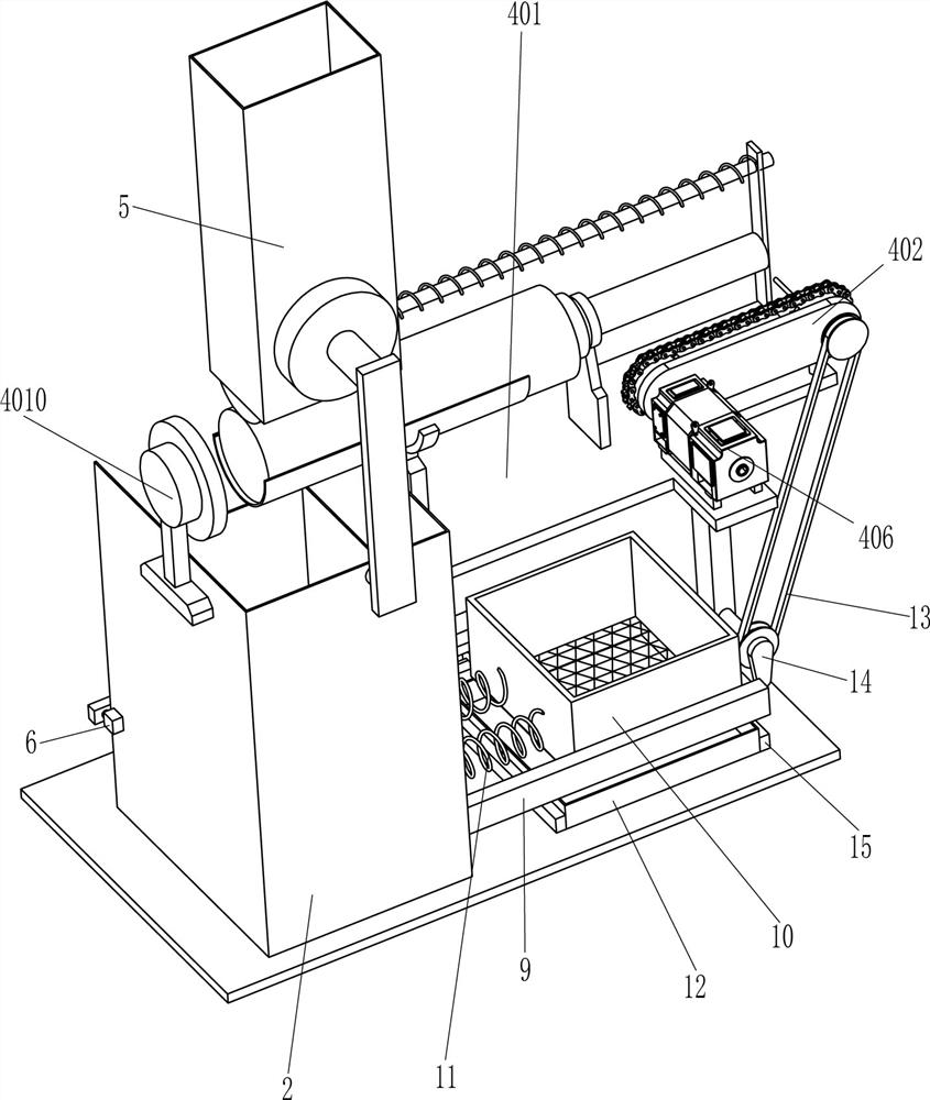
[0027] see figure 2 , Compared with Embodiment 1, the main difference between this embodiment is that in this embodiment, it also includes a guide assembly 9, a screening frame 10, a third spring 11, a frame body 12, a transmission assembly 13 and a cam 14. A guide assembly 9 is connected to the front and rear sides of the lower part of the side surface, and a screening frame 10 is slidably arranged between the inner sides of the guide assemblies 9 on the front and rear sides. A third spring 11 is connected between, the lower part of the rear side of the bracket 4014 is rotatably connected with a cam 14 through a transmission shaft, a transmission assembly 13 is connected between the transmission shaft and the rear end of the left rotation shaft 4015, the transmission assembly 13 is a belt drive, and the cam 14 and the The screening frame 10 is in contact with each other, and a frame body 12 is placed at the rear left side of the top of the bottom plate 1 , and the frame body...


PUM


Abstract

The invention relates to a packaging device, in particular to an automatic compression packaging device for pop cans. The technical problem is how to design a kind of automatic compressing and packaging equipment for pop cans that can replace manual compression of pop cans, saves labor, can continuously compress pop cans, is easy to operate, and has high work efficiency. An automatic compression packing device for pop cans, comprising a base plate, a housing is installed on one side of the base plate, a fixing seat is installed on the outer side of the housing close to the base plate, and a swing rod is rotatably connected to one side of the housing. A block is fixedly connected to the side of the body away from the fixed seat. In the present invention, an appropriate amount of pop cans are placed horizontally in the storage tube, the pop cans fall onto the arc-shaped support plate, and the servo motor is started, so that the pressing bar moves to the right to drive the pop cans to be compressed, and the compressed pop cans fall to the collection frame Inside, there is no need for the operator to manually compress the cans, which saves labor and is convenient to operate, making the work efficiency high.

Description

technical field [0001] The invention relates to a packaging device, in particular to an automatic compression and packaging device for pop-top cans. Background technique [0002] In 1959, ERNIE.C.FRAZE of DRT Company in Teton, Ohio, USA invented the pop-top can, that is, a rivet is formed from the material of the can lid itself, and a pull ring on the outer jacket is then riveted and matched with a suitable score. And become a complete jar lid. This genius invention made a historic breakthrough in metal containers after 50 years of long development. At the same time, it also laid a solid foundation for the development of the canning and beverage industry. The cans originated in the United States and are popular in the United States. After the cans are used, in order to facilitate the collection and processing of the cans, the cans will be compressed and processed. [0003] Existing compression devices, such as the Chinese Patent Publication No. CN108527919A discloses a ca...

Claims


Application Information

Patent Timeline
Patent Type & Authority Patents(China)
IPC IPC(8): B30B9/32B30B15/30B30B15/32B01D33/03
CPCB30B9/321B30B15/30B30B15/32B01D33/0353
Inventor 赖常庆
Owner NANJING HANXIYUE AUTOMATION TECH CO LTD
Why Eureka
Try Eureka