
Flammable liquid storage tank

A storage tank and liquid technology, applied in the field of flammable liquid storage tanks, can solve problems such as tank pressure changes, fire, explosion, tank deformation, etc., to achieve the effect of ensuring balance, preventing fire or explosion, and preventing tank deformation

Inactive Publication Date: 2020-09-18
SHANXI LUAN COAL BASED CLEAN ENERGY
View PDF0 Cites 0 Cited by
  • Summary
  • Abstract
  • Description
  • Claims
  • Application Information

AI Technical Summary

Problems solved by technology

As the ambient temperature changes, the volume of the liquid or gas stored in the storage tank will change, causing the pressure in the tank to change, especially the stored liquid will volatilize due to temperature rise, and liquefy when the temperature decreases. The pressure in the tank changes greatly, which will easily cause the tank to expand or shrink, causing deformation or damage to the tank. Therefore, if figure 1 As shown, the existing storage tanks are often equipped with a breathing valve 2 on the top of the tank body 1 to adjust the pressure in the tank body 1, but for the existing storage tanks equipped with a breathing valve 2, when storing flammable liquid 31, the flammable liquid 31 volatilization will form flammable vapor at the top of the tank body 1, and the air inhaled through the breathing valve 2 will mix with the combustible vapor formed at the top of the tank body 1 to form a flammable and explosive mixture 32. The flammable and explosive mixture 32 encounters lightning strikes, When static electricity, sparks and other ignition sources are used, safety accidents such as fire and explosion may occur

Method used


Image

  • Flammable liquid storage tank
  • Flammable liquid storage tank
  • Flammable liquid storage tank

Examples


Embodiment Construction

[0028] In order to make the object, technical solution and advantages of the present invention clearer, the present invention will be further described in detail below in conjunction with the accompanying drawings.

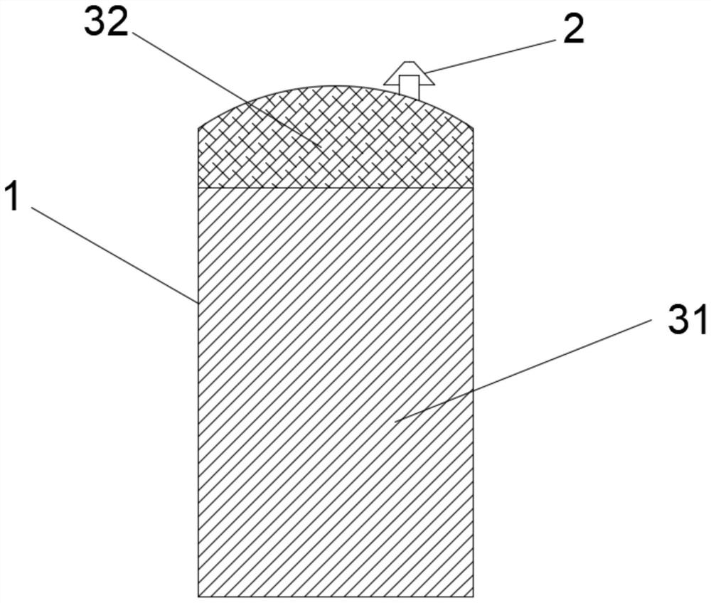
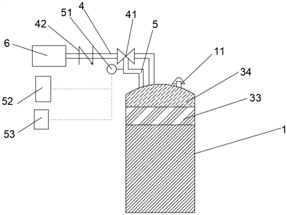
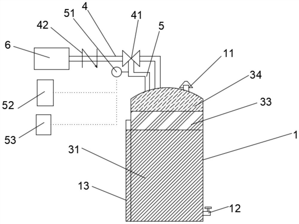
[0029] like figure 2 As shown, the embodiment of the flammable liquid storage tank disclosed by the present invention includes a tank body 1, a pressure relief valve 11, a gas seal main pipe 4, a pressure feedback structure, a pressure regulating valve and an air supply device 6, and the pressure relief valve 11 is arranged on the tank The top of the body 1, the input end and the output end of the air seal main pipe 4 communicate with the top of the gas supply equipment 6 and the inner cavity of the tank body 1 respectively, the pressure regulating valve is arranged on the air seal main pipe 4, and the pressure feedback structure is connected with the tank body 1 respectively. The top of the inner cavity is connected to the pressure regulating valve, the bottom o...


PUM


Abstract

The invention discloses a flammable liquid storage tank. The flammable liquid storage tank comprises a tank body, a pressure relief valve, a gas seal main pipe, a pressure feedback structure, a pressure adjusting valve and gas supply equipment. The pressure relief valve is arranged on the top of the tank body, the input end and the output end of the gas seal main pipe communicate with the gas supply equipment and the top of a tank body inner cavity, the pressure adjusting valve is mounted on the gas seal main pipe, the pressure feedback structure is connected with the top of the tank body inner cavity and the pressure adjusting valve, the gas supply equipment is used for supplying seal gas into the tank body inner cavity through the gas seal main pipe, the seal gas is nonflammable gas, thepressure feedback structure is used for feeding back the pressure of the tank body inner cavity to the pressure adjusting valve, the pressure adjusting valve adjusts the pressure of the seal gas supplied to the tank body inner cavity through the output end of the gas seal main pipe according to the pressure, fed back by the pressure feedback structure, of the tank body inner cavity, according tothe provided flammable liquid storage tank, deforming or damage to the tank body due to the pressure change in the tank body can be prevented, and firing, explosion and other accidents caused by flammable vapor volatilized by the flammable liquid can be avoided.

Description

technical field [0001] The invention relates to the technical field of liquid storage, in particular to a flammable liquid storage tank. Background technique [0002] Storage tanks are containers used to store liquids or gases, and are essential and important infrastructures in industries such as petroleum, chemical industry, grain and oil, food, fire protection, transportation, metallurgy, and national defense. As the ambient temperature changes, the volume of the liquid or gas stored in the storage tank will change, causing the pressure in the tank to change, especially the stored liquid will volatilize due to temperature rise, and liquefy when the temperature decreases. The pressure in the tank changes greatly, which will easily cause the tank to expand or shrink, causing deformation or damage to the tank. Therefore, if figure 1 As shown, the existing storage tanks are often equipped with a breathing valve 2 on the top of the tank body 1 to adjust the pressure in the tan...

Claims


Application Information

Patent Timeline
IPC IPC(8): B65D90/36B65D90/44B65D90/48
CPCB65D90/36B65D90/44B65D90/48
Inventor 宋刚宋鹏张雪军张帅郭玺威申晓伟刘葛君张云李腾腾靳智淏
Owner SHANXI LUAN COAL BASED CLEAN ENERGY
Learn More