Heat exchange tube and air conditioner

A technology for heat exchange tubes and air conditioners, which can be applied to heat sinks, tubular elements, heat exchange equipment, etc., and can solve problems such as limited condensation heat transfer efficiency.

Pending Publication Date: 2020-09-18
GREE ELECTRIC APPLIANCES INC
View PDF0 Cites 0 Cited by
  • Summary
  • Abstract
  • Description
  • Claims
  • Application Information

AI Technical Summary

Problems solved by technology

[0006] Embodiments of the present invention provide a heat exchange tube and an air conditioner to solve the technical problem in the prior art that the condensation heat transfer efficiency is limited due to the stagnation area of ​​the heat exchange tube

Method used


Image

  • Heat exchange tube and air conditioner
  • Heat exchange tube and air conditioner
  • Heat exchange tube and air conditioner

Examples


Embodiment Construction

[0030] In order to make the object, technical solution and advantages of the present invention clearer, the present invention will be described in further detail below in conjunction with the embodiments and accompanying drawings. Here, the exemplary embodiments and descriptions of the present invention are used to explain the present invention, but not to limit the present invention.

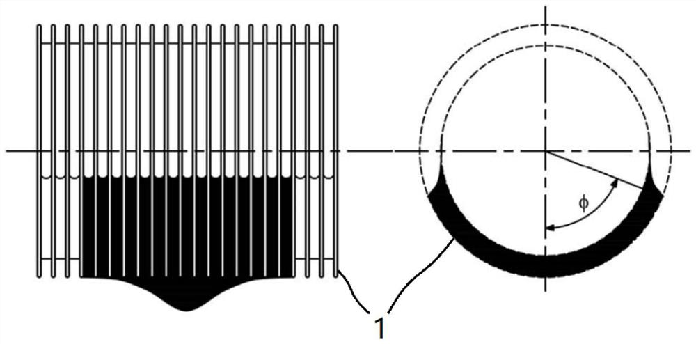
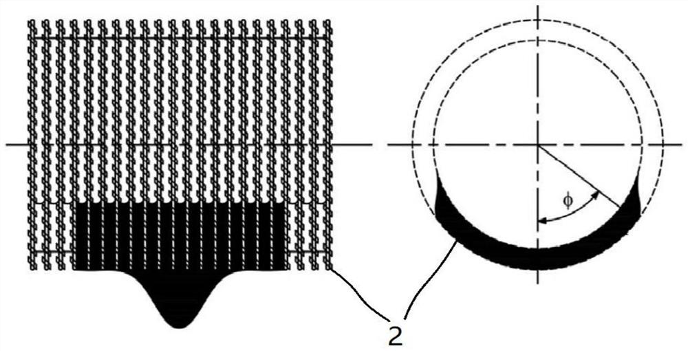
[0031] The existing condensation heat transfer method is mainly based on film condensation. The liquid film formed after steam condensation covers the outer surface of the heat transfer tube and becomes the main thermal resistance that hinders heat transfer. Therefore, in order to improve the condensation heat transfer efficiency, it is necessary not only to increase the heat transfer area, but also to promote the rapid discharge of the condensate film. The steam is in contact with the tube wall, so that the condensation heat transfer coefficient cannot be further improved. With the requiremen...


PUM


Abstract

The invention provides a heat exchange tube and an air conditioner. The heat exchange tube comprises a tube body and fins arranged on the tube body. A first notch and a second notch are formed in thetop of each fin. The depth of each first notch is larger than that of the corresponding second notch. The extending direction of each first notch is arranged at a positive angle relative to the circumferential direction of the corresponding fin. The extending direction of each second notch is arranged at a negative angle relative to the circumferential direction of the corresponding fin. By the adoption of the technical scheme, the bridging phenomenon of liquid between the fins can be weakened, more liquid can flow along with dripping condensate between the adjacent fins, and therefore the condensate retention area is further reduced, the retention angle is further reduced, the heat transfer area of steam and the tube body is increased, and the condensation heat transfer efficiency is improved.

Description

technical field [0001] The invention relates to the technical field of air conditioning, in particular to a heat exchange tube and an air conditioner. Background technique [0002] Condensation of steam outside the horizontal tube is an important heat transfer method, which is widely used in refrigeration and air conditioning, chemical industry, food processing, power plants and other industrial fields: during the heat transfer process, low-temperature fluid circulates in the tube and is taken away by the tube wall The heat of the steam outside the tube causes the steam outside the tube to condense. Over the years, along with the development of heat transfer equipment, both academia and industrial applications have focused on developing more efficient condensing heat transfer surfaces. Among the two methods of condensation, the heat transfer efficiency of bead condensation is much higher than that of film condensation, but its popularization and application in industry is h...

Claims


Application Information

Patent Timeline
Patent Type & Authority Applications(China)
IPC IPC(8): F28F1/12F25B39/04
CPCF25B39/04F28F1/128F28F2215/08
Inventor 武永强胡东兵胡海利王小勇
Owner GREE ELECTRIC APPLIANCES INC
Why Eureka
Try Eureka