
DC transient step response delay test method, system and device

A step-response and time-delay testing technology, applied in measuring devices, measuring electrical variables, instruments, etc., can solve problems such as large test errors, and achieve the effect of avoiding errors and simplifying test loops

Active Publication Date: 2020-09-18
STATE GRID JIANGSU ELECTRIC POWER CO LTD MARKETING SERVICE CENT +4
View PDF9 Cites 4 Cited by
  • Summary
  • Abstract
  • Description
  • Claims
  • Application Information

AI Technical Summary

Problems solved by technology

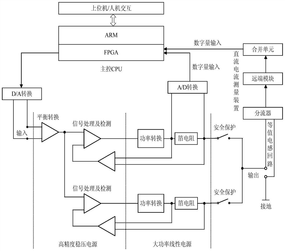
[0005] The invention provides a DC transient step response delay test method, system and device, which solves the problem of relatively large test errors in existing test methods

Method used


Image

  • DC transient step response delay test method, system and device
  • DC transient step response delay test method, system and device
  • DC transient step response delay test method, system and device

Examples


Embodiment Construction

[0039] The present invention will be further described below in conjunction with the accompanying drawings. The following examples are only used to illustrate the technical solution of the present invention more clearly, but not to limit the protection scope of the present invention.

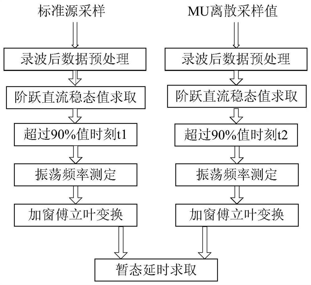
[0040] like figure 1 As shown, a DC transient step response delay test method includes the following steps:

[0041] Step 1, recording and sampling the standard source signal and the second-order step oscillation attenuation current signal and performing preprocessing.

[0042] The sudden change is recorded and sampled, and the sudden change algorithm is as follows:

[0043] Δi=|[i(t)-i(t-T)]-[i(t-T)-i(t-2T)]|

[0044] Among them, i is the instantaneous value of the current, t is the current moment, and T is a power frequency cycle. When Δi is greater than the preset startup customization, the wave recording and sampling will be started.

[0045] Step 2, use generalized polynomial fitting to...


PUM


Abstract

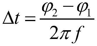
The invention discloses a DC transient state step response time delay test method. The method comprises the following steps: sampling a standard source signal and a second step oscillation attenuationcurrent signal; solving steady-state direct-current components of the standard source signal and the second-step oscillation attenuation current signal; acquiring step moments of the standard sourcesignal and the second-step oscillation attenuation current signal according to the steady-state direct-current component; solving the oscillation frequency of the second-order step oscillation attenuation current signal after the step and before the stability according to the steady-state direct-current component; adopting windowed Fourier transform to solve fundamental wave phases of the standardsource signal and the second-order step oscillation attenuation current signal; and according to the fundamental wave phase and the oscillation frequency, solving the DC transient state step responsetime delay. The invention further discloses a corresponding system and device. According to the method, direct-current transient step response delay calculation is realized through alternating-current phase compensation of windowed Fourier transform, and errors caused by interpolation calculation in a traditional method are avoided.

Description

technical field [0001] The invention relates to a DC transient step response delay testing method, system and device, and belongs to the field of UHV DC transmission testing. Background technique [0002] With the rapid development of high-power fully-controlled power electronic devices and the continuous improvement of the manufacturing level of DC grids, the voltage source DC transmission (VSC-HVDC) based on insulated gate bipolar thyristors (IGBTs) has attracted more and more attention. application. The emergence of voltage source DC transmission makes the DC control and protection system have higher and higher requirements for the delay of the DC measurement device, especially the step response delay. The DC current measurement device is a digital output, which inevitably involves the problem of transient response time of signal transmission, and this problem is one of the core indicators that all equipment on the bay layer, especially the control and protection equipme...

Claims


Application Information

Patent Timeline
IPC IPC(8): G01R35/02
CPCG01R35/02
Inventor 陈刚徐敏锐黄奇峰卢树峰王忠东杨世海李志新汤汉松陆子刚罗强陈文广周东顶吴桥郭家豪陈飞龚文
Owner STATE GRID JIANGSU ELECTRIC POWER CO LTD MARKETING SERVICE CENT
Learn More