Centrifugal flight load and illusion simulation device

A flight load and simulation device technology, applied in the field of simulated flight, can solve the problems of severe bearing force, increased weight of yaw frame, and difficulty in equipment installation and debugging, so as to achieve reasonable matching of bearing force and overcome bearing force. Harsh, the effect of realizing the compact layout of the shafting

Pending Publication Date: 2020-09-18
GENERAL ENG RES INST CHINA ACAD OF ENG PHYSICS
View PDF1 Cites 2 Cited by
  • Summary
  • Abstract
  • Description
  • Claims
  • Application Information

AI Technical Summary

Problems solved by technology

[0007] However, the "four-degree-of-freedom helicopter dynamic flight simulator" in this patent adopts a double-layer layout structure, that is, the main drive motor and reducer are located on the ground floor, and a special basement is required for layout. This disadvantage is that the civil construction is complicated. The cost is high, and it is difficult to install and debug the equipment
[0008] The position of the center of mass of the cockpit and the position of the main shaft support point in this patent are in two planes, which causes the yaw frame to bear an excessive overturning moment, and at the same time, the rotating arm is subjected to a large bending moment, which aggravates the deformation of the rotating arm during movement, and requires the yaw frame to have Sufficient strength and stiffness to increase the weight of the yaw frame
[0009] The counterweight and the center of mass of the cockpit system in this patent are not on a line parallel to the ground, forming an unbalanced force couple, which is likely to cause vibration and cause severe bearing stress

Method used


Image

  • Centrifugal flight load and illusion simulation device
  • Centrifugal flight load and illusion simulation device
  • Centrifugal flight load and illusion simulation device

Examples


Embodiment Construction

[0031]In order to make the object, technical solution and advantages of the present invention more clear, the present invention will be further described in detail below in conjunction with the accompanying drawings and embodiments. It should be understood that the specific embodiments described here are only used to explain the present invention, and are not intended to limit the present invention, that is, the described embodiments are only some of the embodiments of the present invention, but not all of the embodiments. The components of the embodiments of the invention generally described and illustrated in the figures herein may be arranged and designed in a variety of different configurations.

[0032] Accordingly, the following detailed description of the embodiments of the invention provided in the accompanying drawings is not intended to limit the scope of the claimed invention, but merely represents selected embodiments of the invention. Based on the embodiments of t...


PUM


Abstract

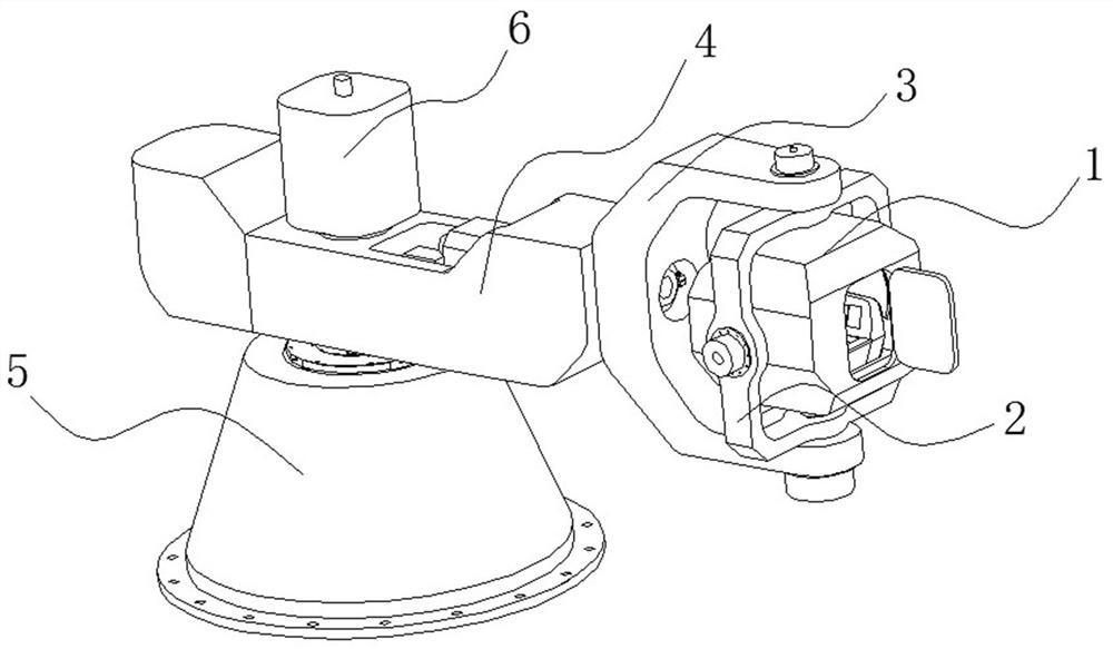
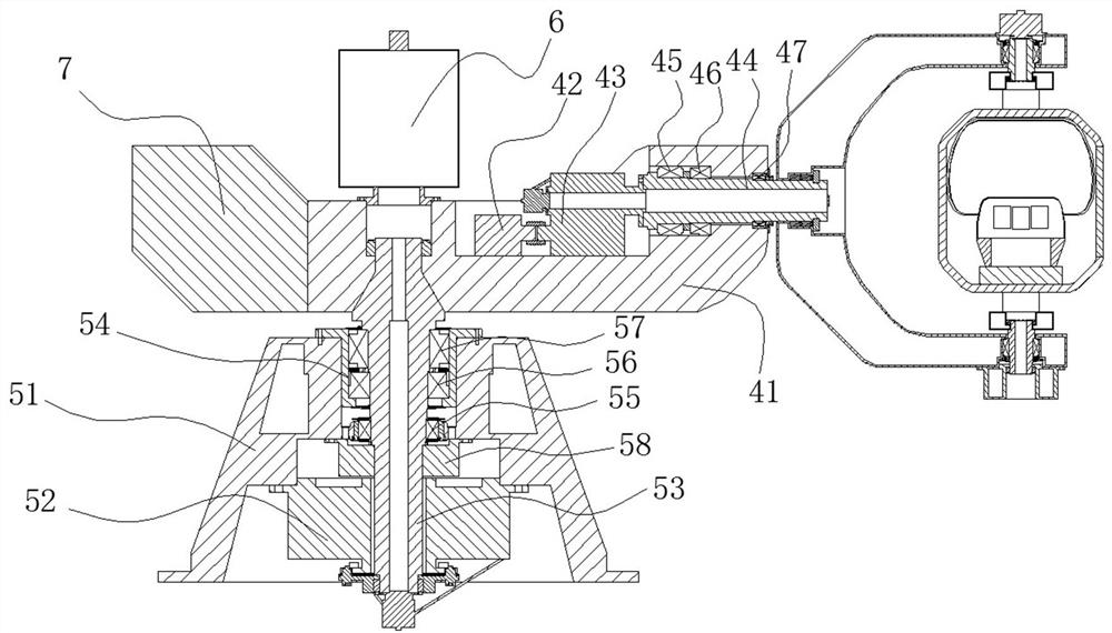
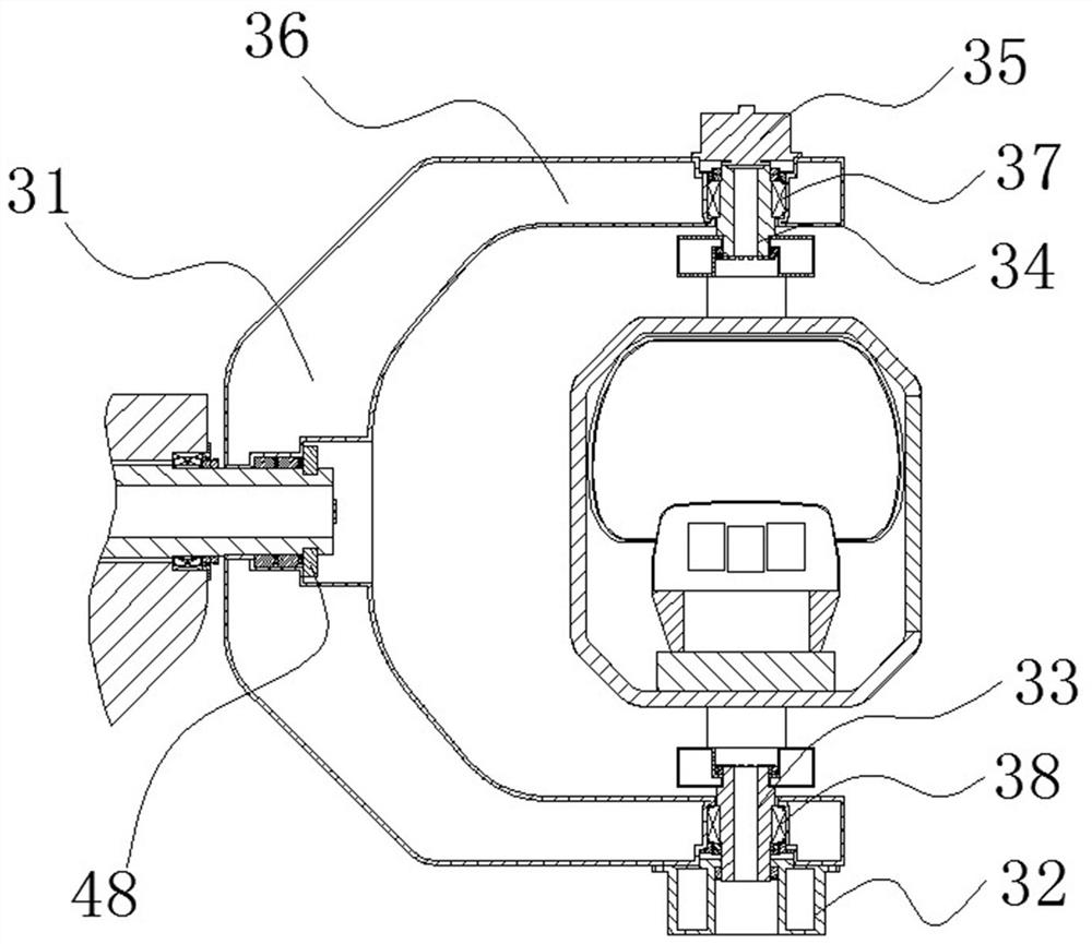
The invention relates to the technical field of simulated flight, and specifically discloses a centrifugal flight load and illusion simulation device. The centrifugal flight load and illusion simulation device comprises a transmission supporting system, a rotating arm system, a yawing frame system, a pitching frame system and a cockpit system; wherein the transmission supporting system supports the rotating arm system; the rotating arm system is provided with the pitching frame system and drives the pitching frame system to rotate around a connecting point of the pitching frame system and therotating arm system; the yawing frame system is arranged on the pitching frame system, and the pitching frame system drives the yawing frame system to rotate around a connecting point of the pitchingframe system and the yawing frame system; and the cockpit system is arranged on the yawing frame system, and the yawing frame system drives the cockpit system to rotate around a connecting point of the cockpit system and the yawing frame system. The centrifugal flight load and illusion simulation device has the advantages that a main shaft rotates to generate overload acceleration, three degrees of freedom of yawing, pitching and rolling relative to a human body coordinate system are generated at the tail end of a rotating arm, a trained pilot sits in a cockpit system and bears centrifugal overload acceleration and spatial three-attitude-angle movement, and spatial orientation obstacle simulation training is achieved.

Description

technical field [0001] The invention relates to the technical field of flight simulation, in particular to a centrifugal flight load and illusion simulation device. Background technique [0002] A centrifugal flight load and space orientation obstacle simulation device is a simulation device based on the centrifuge platform, which uses the rotation of the centrifuge to generate continuous overload acceleration, and installs a three-degree-of-freedom rotating frame system at the end of the centrifuge, which can realize accurate simulation of load value and direction , At the same time, the attitude simulation under the overload environment can be carried out. [0003] The flight load simulation can train the pilot's anti-overload ability. During the maneuvering flight of high-performance fighter jets, when there is an excessive head-to-foot overload, the blood supply to the brain is reduced and the brain tissue is hypoxic, which in turn causes gray vision, black vision and e...

Claims


Application Information

Patent Timeline
Patent Type & Authority Applications(China)
IPC IPC(8): G09B9/08
CPCG09B9/085
Inventor 宋琼何阳蒋春梅尹娇妹黎启胜白俊林刘婷婷
Owner GENERAL ENG RES INST CHINA ACAD OF ENG PHYSICS
Why Eureka
Try Eureka