Beam-rail integrated structure and medium-low speed maglev track beam with same

A maglev track, low-speed technology, applied in tracks, roads, buildings, etc., can solve the problems of high track structure, difficult installation, waste of materials, etc., to achieve good structural stress performance, good track smoothness, and avoid structural failures Effect

Pending Publication Date: 2019-01-18
CHINA RAILWAY MAGLEV TRANSPORTATION INVESTMENT CONSTR CO LTD
View PDF12 Cites 0 Cited by
  • Summary
  • Abstract
  • Description
  • Claims
  • Application Information

AI Technical Summary

Problems solved by technology

There are many problems in the low-speed maglev bridge of the prior art: (1) the track structure height is relatively large, the structure height is increased on the bridge and the roadbed, and the tunnel section is increased in the tunnel, which increases the load between the track and the beam operating distance, especially in figure 2 In the case of the superelevation of the curve shown, the support structure not only transmits the gravity load of the vehicle and the track itself, but also bears the transverse shear force, which is easy to be between the steel beam and the bearing platform and between the F rail and the fastener. Faults occur, which affect the safety and reliability of the track beam structure; (2) The track structure is complex, including F rails, steel beams, fasteners, rail bearing platforms and their mechanical connection devices, which is not only difficult to install, but also expensive ; (3) The second-stage load of the track structure is relatively large, resulting in a large amount of engineering work for the bridge structure; (4) In the design of the bridge structure, the stiffness and strength provided by the track structure are generally not considered, which wastes materials; (5) The F rail is located at On the support of the steel beams with large intervals, under the action of the vehicle load, the F rail undergoes continuous vertical bending deformation, resulting in short-wave irregularities on the rail surface

Method used


Image

  • Beam-rail integrated structure and medium-low speed maglev track beam with same
  • Beam-rail integrated structure and medium-low speed maglev track beam with same
  • Beam-rail integrated structure and medium-low speed maglev track beam with same

Examples


Embodiment Construction

[0038]In order to make the object, technical solution and advantages of the present invention clearer, the present invention will be further described in detail below in conjunction with the accompanying drawings and embodiments. It should be understood that the specific embodiments described here are only used to explain the present invention, not to limit the present invention. In addition, the technical features involved in the various embodiments of the present invention described below can be combined with each other as long as they do not constitute a conflict with each other.

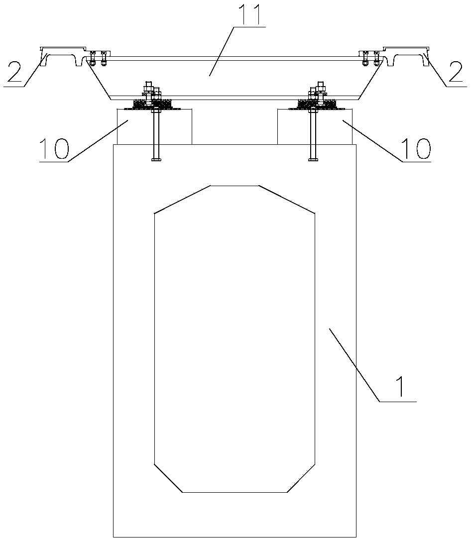
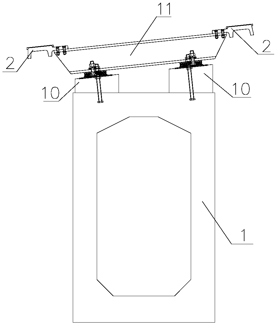
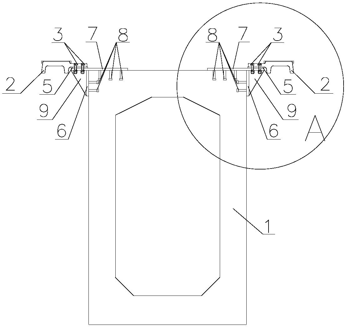
[0039] Aiming at a series of problems existing in the low-speed maglev track beam structure in the prior art, the present invention provides a medium-low speed maglev track beam with a beam-rail integrated structure, and the beam-rail integrated structure is symmetrically arranged on the top of the concrete beam. The beam-rail integrated structure includes F rails and connection devices, wherein ...


PUM


Abstract

The invention discloses a beam-rail integrated structure, which comprises an f rail and a concrete beam, wherein the f rail is arranged between the f rail and the concrete beam (1); the connecting device comprises parallel and perpendicular to the concrete beam (1) is arranged on the top of the concrete beam or pre-buried in the concrete beam (1) a first connecting piece and a second connecting piece, wherein the first connecting piece is used for fixing the f rail and the first connecting piece. The invention further discloses a medium and low speed magnetic levitation track beam with the beam and rail integrated structure. According to the beam and rail integrated structure, the height of the whole rail beam structure is greatly reduced, the motion of a vehicle body borne by the f rail and the like are directly transmitted through an integrated structure of the beam and rail, and the curve ultrahigh-section beam. The rail integrated structure directly bears the transverse shearing acting force caused by inclination of the rail, so that not only is the rail improved, but also the rail. The force transmission efficiency of the beams is improved, and the structure faults among the rail beams caused by the load action are effectively avoided.

Description

technical field [0001] The invention belongs to the technical field of maglev rail transit, and more specifically relates to a beam-rail integrated structure and a medium-low speed maglev rail beam with the structure. Background technique [0002] Medium and low-speed maglev transportation is a new type of rail transportation mode optimized and innovated on the basis of traditional railway technology after more than 100 years of development. Medium and low-speed maglev transportation has the advantages of low noise, low vibration, low radiation, low cost, strong climbing ability, and small turning radius. It not only saves a lot of land resources, but also provides safe, reliable, energy-saving and environmental protection for the development of urban traffic. The new choice is a new development direction in the field of urban transportation. In recent years, great achievements have been made in the theoretical research and engineering application of medium and low speed ma...

Claims


Application Information

Patent Timeline
Patent Type & Authority Applications(China)
IPC IPC(8): E01B25/30
CPCE01B25/30
Inventor 龚俊虎谢海林鄢巨平张家炳
Owner CHINA RAILWAY MAGLEV TRANSPORTATION INVESTMENT CONSTR CO LTD
Why Eureka
Try Eureka