
a cleaning system

A cleaning system and cleaning room technology, applied in the field of cleaning systems, can solve the problems of steam heat energy and waste of clean water resources, and achieve the effect of reducing emissions

Active Publication Date: 2022-04-22
WUXI ASIA ELECTRONICS INTELLIGENT EQUIP CO LTD
View PDF5 Cites 0 Cited by
  • Summary
  • Abstract
  • Description
  • Claims
  • Application Information

AI Technical Summary

Problems solved by technology

In the existing cleaning system, the steam and clean water are usually discharged after only one use, which is a waste of steam heat energy and clean water resources

Method used


Image

  • a cleaning system
  • a cleaning system
  • a cleaning system

Examples


Embodiment 1

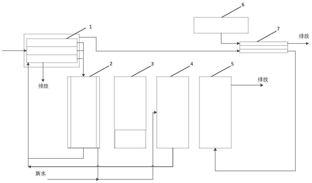
[0043] This embodiment provides a cleaning system, such as figure 1 shown, including:

[0044] Gas-fired boiler 1 is capable of feeding in natural gas and burning natural gas to heat water to form water vapor. It has a combustion chamber 11 and several steam generating chambers 12. Combustion chamber 11 has a high-temperature waste gas outlet, and each steam generating chamber 12 has a water vapor outlet;

[0045] The steam cleaning chamber 2 is cylindrical and has a collection tank at the bottom. The collection tank is divided into an intermediate collection tank for collecting the condensed water dripping from the workpiece placed in the center of the steam cleaning chamber 2, and collecting the condensed water from the four sides of the steam cleaning chamber 2. Peripheral collection troughs for condensate dripping on the interior walls;

[0046] The cleaning liquid cleaning chamber 3 is a immersion equipment, and the bottom of the cleaning liquid cleaning chamber 3 is equ...

Embodiment 2

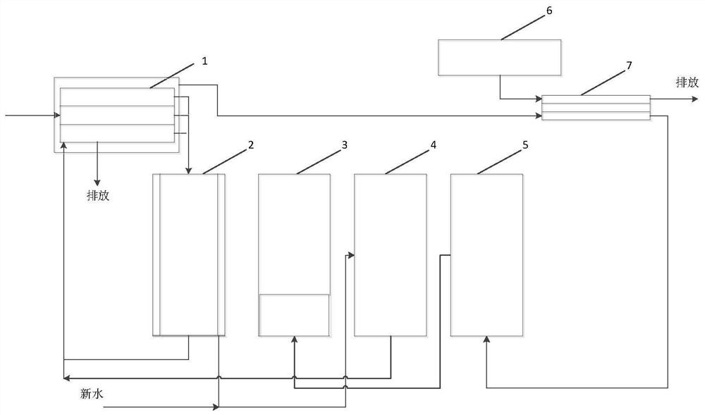
[0058] This embodiment provides a cleaning system, such as figure 2 shown, including:

[0059] On the basis of Embodiment 1, the gas flowing out of the drying chamber 5 is passed into the bubble generator 31 through the pressurization device 8, so that bubbles are generated in the cleaning liquid cleaning chamber 3 to improve the cleaning effect; it should be pointed out that the pressurization device 8 is to provide sufficient pressure for the bubbles in the cleaning liquid cleaning chamber 3 to emerge;

Embodiment 3

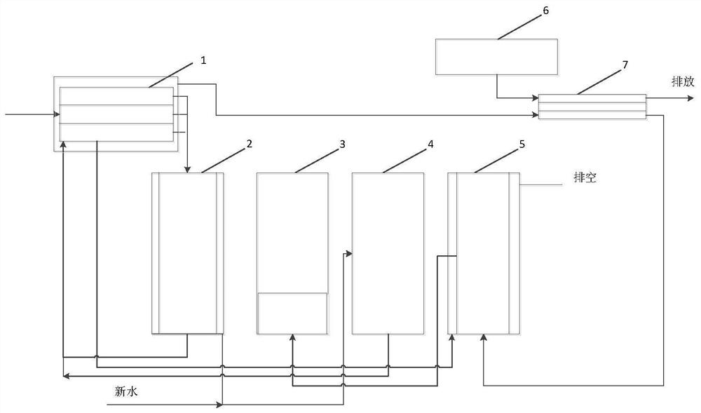
[0061] This embodiment provides a cleaning system, such as image 3 shown, including:

[0062] On the basis of embodiment 2, the side wall of drying chamber 5 has jacket or pipeline, and the jacket of drying chamber 5 or pipeline are connected with the water outlet of steam generating chamber 12, and the remaining liquid of steam generating chamber 12 and guide steam generating chamber The condensed water in the intermediate collection tank of 12 is passed into the jacket or pipeline of the drying chamber 5 to heat the drying chamber 5 and maintain the temperature of the drying chamber 5.


PUM


Abstract

This application relates to a cleaning system, which is composed of a gas boiler, a steam cleaning room, a cleaning liquid cleaning room, a clean water cleaning room and a drying room. Dirty condensed water and clean condensed water dripping on the wall of the cleaning chamber, and the relatively clean condensed water is sent to the clean water cleaning chamber for direct use. Dirty condensed water is returned to the gas boiler for re-evaporation, but part of the water is retained, and then the condensed water introduced into the middle collection tank of the steam cleaning chamber cleans the steam generating chamber to prevent impurities from clogging the gas boiler. Through the above settings, the comprehensive utilization of heat energy and water is realized, and the discharge of sewage is reduced.

Description

technical field [0001] The present application belongs to the technical field of cleaning equipment, and in particular relates to a cleaning system. Background technique [0002] In the prior art, for some workpieces, steam cleaning and cleaning with cleaning solution are required. The usual operation steps are to transport the workpieces to the steam cleaning chamber (steam cleaning), In the cleaning liquid cleaning chamber (cleaning liquid cleaning) and the clean water cleaning room (clean water cleaning to remove the cleaning liquid), the cleaning is carried out in sequence. The above cleaning process needs to use steam, cleaning liquid, clean water, etc. In the existing cleaning system, the steam and clean water are usually discharged after only one use, which is a waste of steam heat energy and clean water resources. Contents of the invention [0003] The technical problem to be solved by the present invention is to provide a cleaning system capable of comprehensive ...

Claims


Application Information

Patent Timeline
Patent Type & Authority Patents(China)
IPC IPC(8): B08B3/02B08B3/10F26B9/06F26B21/14F28D21/00
CPCB08B3/02B08B3/10F26B9/06F26B21/14F28D21/0014Y02P70/10
Inventor 钱诚李刚童建
Owner WUXI ASIA ELECTRONICS INTELLIGENT EQUIP CO LTD
Learn More