Hydraulic punching machine

A technology of hydraulic punch and hydraulic cylinder, which is applied to the cleaning methods, cleaning methods and utensils, chemical instruments and methods using gas flow, etc. and other problems to achieve the effect of improving air tightness

Inactive Publication Date: 2020-09-22
孙逸民
View PDF6 Cites 2 Cited by
  • Summary
  • Abstract
  • Description
  • Claims
  • Application Information

AI Technical Summary

Problems solved by technology

[0003] However, when the hydraulic punching press in the prior art is stamping the steel plate, the steel plate will be bent and plunged into the die groove under the pressure of the stamping plate, and metal residues may appear in the bending part of the steel plate during bending, and the metal residues will leak into the die. The inside o

Method used


Image

  • Hydraulic punching machine
  • Hydraulic punching machine
  • Hydraulic punching machine

Examples


Embodiment 1

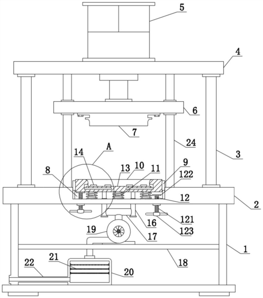
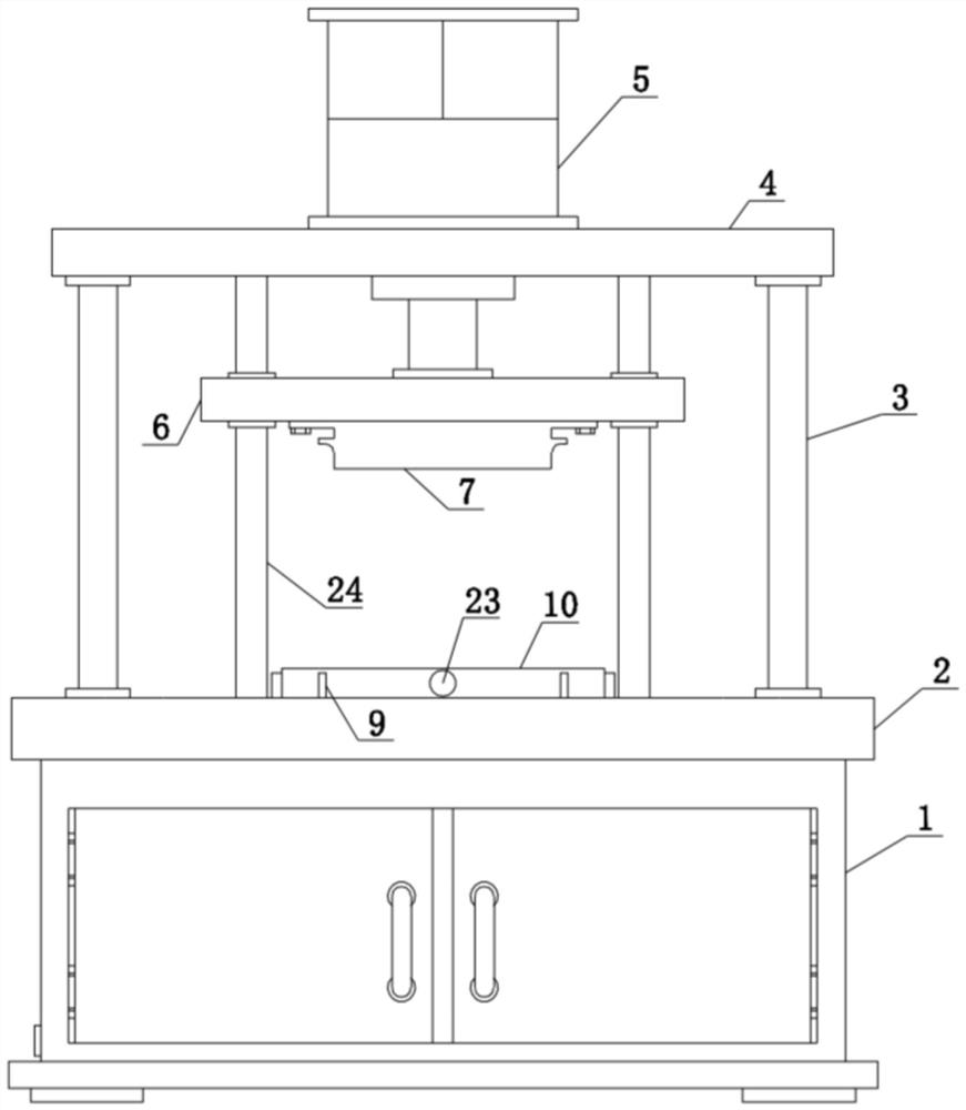
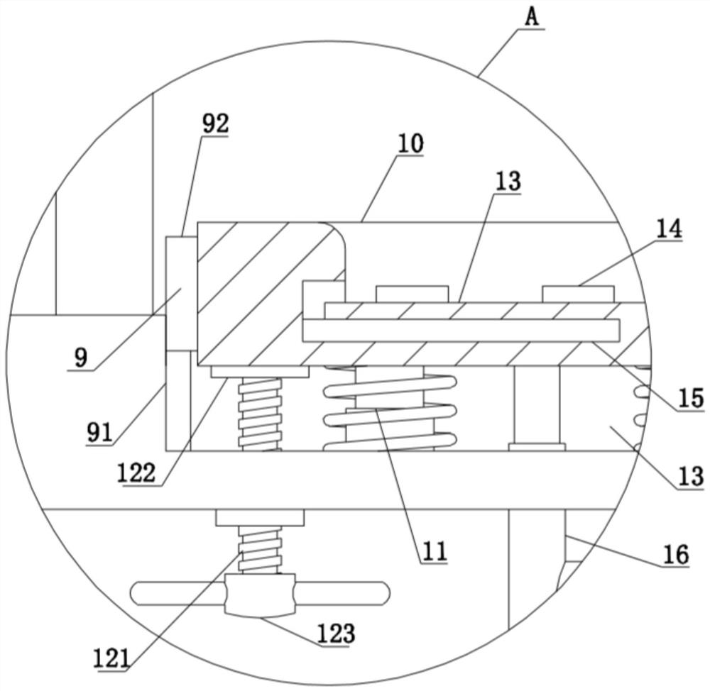
[0034] see Figure 1-Figure 3 , a hydraulic press, comprising a body 1, the upper end of the body 1 is fixedly connected with a base 2, both sides of the upper end of the base 2 are fixedly connected with fixed columns 3, and the upper end of the fixed column 3 is fixedly connected with a top plate 4 , both sides between the base 2 and the top plate 4 are fixedly connected with a guide shaft 24, and the guide shaft 24 runs through the press plate 6 and is slidingly connected with it, and when the hydraulic cylinder 5 pushes the press plate 6 to move, it runs through the press plate 6 for two The guide shaft 24 on the side can make the push plate move up and down in a straight line, making the push plate move more stably. The upper end of the top plate 4 is fixedly connected with a hydraulic cylinder 5, and the end of the telescopic shaft at the lower end of the hydraulic cylinder 5 runs through the top plate 4 and is fixed. A pressing plate 6 is connected, the lower end of the...


PUM


Abstract

The invention discloses a hydraulic punching machine, and belongs to the field of the hydraulic punching machine. The hydraulic punching machine comprises a machine body, and the upper end of the machine body is fixedly connected with a base. The two sides of the upper end of the base are fixedly connected with fixed columns, the upper ends of the fixed columns are fixedly connected with a top plate, and the upper end of the top plate is fixedly connected with a hydraulic cylinder. When a steel plate is punched and bent, the generated waste debris is transmitted to a suction port through suction force generated by a fan, and the waste debris is sucked through the suction port and then is conveyed to a collection box. Layers of filter plates made of magnets are arranged in the collection box and absorb the metal debris, thus the metal debris is conveniently collected, and the influence of too much waste debris in a die slot on the punching of the steel plate is avoided. Moreover, An insertion column in a jacking mechanism is pushed, the insertion column moves to jack a jacking column in a movable hole, and the jacking column can take the steel plate at the upper end of the die slotout of the die slot. Thus, the finished steel plate is conveniently taken out.

Description

technical field [0001] The invention relates to the field of hydraulic presses, more specifically, to a hydraulic press. Background technique [0002] The hydraulic punch press is a punch press that uses a hydraulic cylinder to generate compression force. The hydraulic punch press was invented by Joseph Bramah in England. He invented the hydraulic punch press in 1795 and applied for a patent. Brahma applied his concept to the punch press after studying the literature on fluid motion at the time. When manufacturing mechanical parts, hydraulic punching machines are generally used, and hydraulic punching machines are already an indispensable equipment in industrial manufacturing. [0003] However, when the hydraulic punching press in the prior art is stamping the steel plate, the steel plate will be bent and plunged into the die groove under the pressure of the stamping plate, and metal residues may appear in the bending part of the steel plate during bending, and the metal re...

Claims


Application Information

Patent Timeline
IPC IPC(8): B21D5/02B21D45/04B08B5/04
CPCB08B5/04B21D5/02B21D45/04
Inventor 孙逸民
Owner 孙逸民
Why Eureka
Try Eureka