Ceramic processing device
A technology of ceramic processing and transmission mechanism, which is applied in spraying devices, ceramic molding machines, manufacturing tools, etc. It can solve the problems of lowering the efficiency of glazing processing, affecting the quality of ceramic products, and reducing the concentration of glaze liquid, so as to improve the quality of glazing, Uniform glazing and quality-enhancing effects
- Summary
- Abstract
- Description
- Claims
- Application Information
AI Technical Summary
Problems solved by technology
Method used
Image
Examples
specific Embodiment approach 1
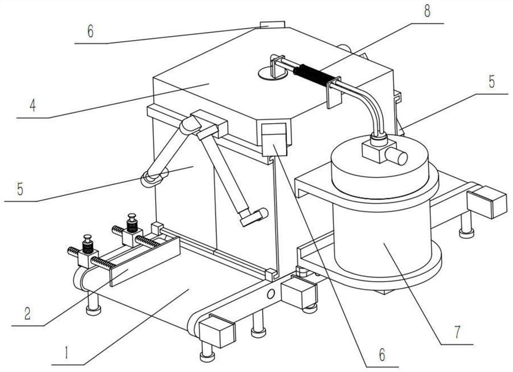
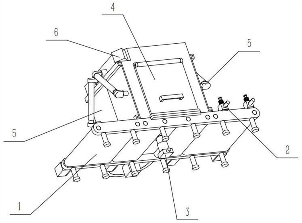
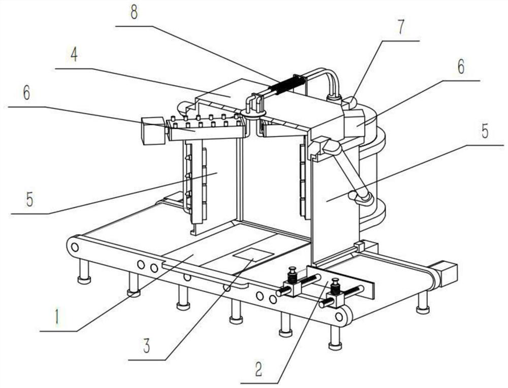
[0034] Combine below Figure 1-12 Describe this embodiment, a ceramic processing device, including a transmission mechanism 1 and a limit mechanism 2, the ceramic processing device also includes a lifting mechanism 3, a protection mechanism 4, a closing mechanism 5, a spraying mechanism 6, a liquid supply mechanism 7 and a telescopic tube Mechanism 8, the limit mechanism 2 is fixedly connected to the right side of the upper end of the transmission mechanism 1, the lifting mechanism 3 is arranged in the middle of the transmission mechanism 1, the protection mechanism 4 is fixedly connected to the middle of the upper end of the transmission mechanism 1, the There are two closing mechanisms 5, and the two closing mechanisms 5 are respectively slidingly connected to the front and rear ends of the protective mechanism 4. There are two spraying mechanisms 6, and the two spraying mechanisms 6 are centrally symmetrical and fixedly connected in the protective mechanism 4. The top of th...
specific Embodiment approach 2
[0037] Combine below Figure 1-12 Describe this embodiment, this embodiment will further explain the first embodiment, the transmission mechanism 1 includes a transmission rack 1-1, a conveyor belt I1-2, a conveyor belt II1-3, a motor I1-4, a motor II1-5 and a loading slot 1-6, two conveyor belts I1-2 and two conveyor belts II1-3 are provided, the two conveyor belts I1-2 are respectively arranged on both sides of the upper end of the conveyor frame 1-1, and the two conveyor belts II1-3 are respectively arranged on two sides On the inner side of a conveyor belt I1-2, two motors I1-4 and two motors II1-5 are provided, and the two motors I1-4 and two motors II1-5 are fixedly connected to the transmission frame 1-1. On the left side, the output shafts of the two motors I1-4 are respectively fixedly connected with the two front pulleys of the front conveyor belt I1-2 and the conveyor belt II1-3, and the output shafts of the two motors II1-5 are respectively connected with the rear ...
specific Embodiment approach 3
[0040] Combine below Figure 1-12 Describe this embodiment, this embodiment will further explain the second embodiment, the limit mechanism 2 includes a limit plate 2-1, a gear rod 2-2, an adjustment frame 2-3, an insertion rod 2-4 and a spring tube I2-5, two gear rods 2-2 are provided, and the two gear rods 2-2 are fixedly connected to the right end of the limit plate 2-1, and the adjustment frame 2-3 is provided with two, two The gear rods 2-2 are respectively slidably connected in the two adjustment frames 2-3, and two insertion rods 2-4 are provided, and the two insertion rods 2-4 are respectively slidably connected in the two adjustment frames 2-3, And the two insertion rods 2-4 are respectively inserted into the two corresponding tooth slots on the two gear rods 2-2, and the spring tube I2-5 is provided with two, and the two spring tubes I2-5 are respectively sleeved on the two On the outer side of each insertion rod 2-4, the upper ends of the two spring tubes I2-5 are ...
PUM
 Abstract
Description
Claims
Application Information
 - R&D
- Intellectual Property
- Life Sciences
- Materials
- Tech Scout
- Unparalleled Data Quality
- Higher Quality Content
- 60% Fewer Hallucinations
Browse by: Latest US Patents, China's latest patents, Technical Efficacy Thesaurus, Application Domain, Technology Topic, Popular Technical Reports.
© 2025 PatSnap. All rights reserved.Legal|Privacy policy|Modern Slavery Act Transparency Statement|Sitemap|About US| Contact US: help@patsnap.com


