PHC pipe pile construction method

A technology of PHC pipe piles and construction methods, which is applied in the direction of sheet pile walls, foundation structure engineering, construction, etc., and can solve pipe pile side friction resistance and weakening of pile end resistance, uneven thickness of multi-layer silty clay, and soil squeezing effect Loss and other problems, to reduce the difficulty of penetration, increase the density and quantity of the skeleton, and increase the quantity and density of the structure

Active Publication Date: 2020-09-22
福建省华策建设集团有限公司
View PDF4 Cites 13 Cited by
  • Summary
  • Abstract
  • Description
  • Claims
  • Application Information

AI Technical Summary

Problems solved by technology

[0003] However, for complex geology such as soft soil layers, muddy soil layers, and hard soil interlayers, the conventional PHC pipe pile penetration construction technology achieves unsatisfactory results. The multi-layer silty clay with calcareous concretions is often difficult to meet the two control indicators of penetration effective pile length and final pressure at the same time. In addition, multi-layer silty clay often has uneven thickness, which increases the Difficulty of pile penetration construction
[0004] If the construction method of drilling the pilot hole first and then penetrating the pipe pile can reduce the penetration difficulty of the pipe pile, but due to the release of the pile side and pile bottom stress, the soil squeezing effect will be partially lost, that is, the side friction of the pipe pile Resistance and pile tip resistance have been weakened

Method used


Image

  • PHC pipe pile construction method
  • PHC pipe pile construction method
  • PHC pipe pile construction method

Examples


Embodiment 1

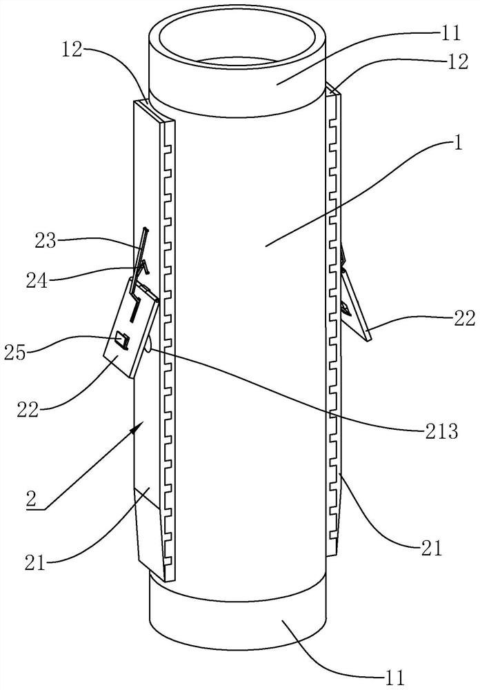
[0056] Embodiment 1: as figure 1 As shown, it is a PHC pipe pile structure disclosed by the present invention, which includes a pipe pile 1 and a metal skeleton assembly 2 installed on the pipe pile 1; wherein the upper and lower ends of the pipe pile 1 are provided with pile head caps 11 .

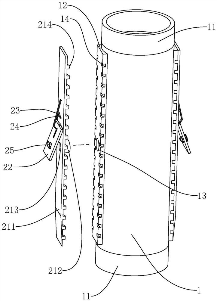
[0057] Such as figure 1 As shown, the outer peripheral surface of the pipe pile 1 is protrudingly configured with a plurality of plane platforms 12, the length direction of the plane platforms 12 is arranged along the axial direction of the pipe pile 1, and each plane platform 12 is evenly arranged along the circumference of the pipe pile 1; the plane platforms 12 A grout hole 13 connected to the inner cavity of the pipe pile 1 is opened through it.

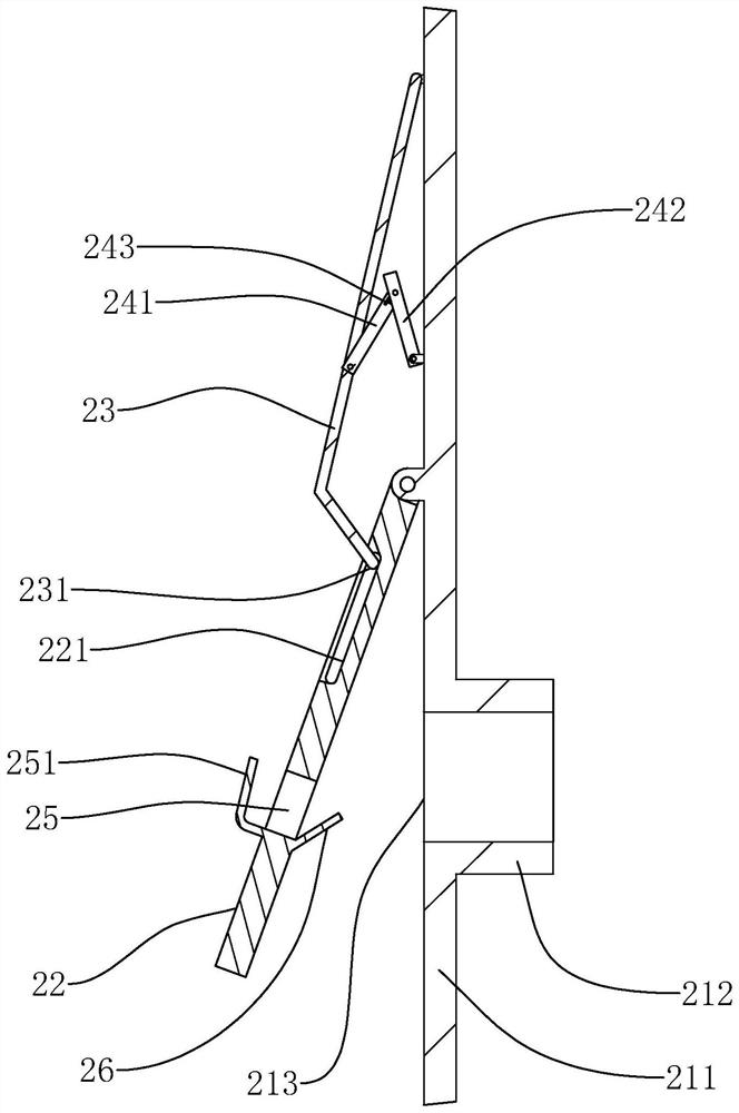
[0058] Such as figure 1 , figure 2 As shown, the skeleton assembly 2 includes a carrier body 21, a flap plate 22, a skeleton rod 23 and a linkage frame 24; the carrier body 21 includes a fixed plate 211 and a fixed sleeve 212, the fixed ...

Embodiment 2

[0066] Embodiment 2: The difference with Embodiment 1 is that, as Image 6 As shown, there are two flip plates 22, and the flip plates 22 are arranged symmetrically up and down along the through hole 213. The free end of flip plate 22 is positioned at the outside of top flip plate 22, and the outer side of the extension end 251 of the louver hole 25 of top flip plate 22 blocks the entrance end of the louver hole 25 of the flip plate 22 below, and the flip below The end of the deflector 26 of the plate 22 abuts against the outer surface of the extension end 251 of the louver hole 25 of the flip plate 22 above; The escape groove 222 of the plate 26.

[0067] During pile pressing, the louver hole 25 of the lower flap 22 is closed, so that the pile side soil is difficult to enter through the louver hole 25 of the lower flap 22, and in the initial stage of pile pressing, the pile side soil is more likely to block the lower flap 22. The louver hole 25, that is, the pile side soil ...

Embodiment 3

[0069] Embodiment 3: a kind of construction method based on embodiment 1 or embodiment 2 structure disclosed by the present invention, comprises the following steps:

[0070] S1. Construction preparation:

[0071] S1.1. Technical preparation, familiarize yourself with and review construction drawings and relevant technical documents; master geological survey data and technical and economic data; prepare construction organization design, determine construction plan, and propose measures to save labor and materials and reduce process costs.

[0072] S1.2. Preparation of construction materials, determine the demand for materials, construction machinery, equipment, tools, etc. at each stage, and arrange transportation and entry in time to meet the needs of continuous construction.

[0073] S1.3. According to the geological exploration information, a grout hole 13 is opened at a specific position of the pipe pile 1, and the specific position is the part of the pipe pile 1 where the s...


PUM


Abstract

The invention relates to a PHC pipe pile construction method. The PHC pipe pile construction method comprises the following steps including the first step of construction preparation, the second stepof measuring, paying-off and pile distribution, the third step of long spiral drilling machine arrival, the fourth step of long spiral drilling machine hole drilling and guiding, the fifth step of drill rod elevating and soil cleaning, the sixth step of pile pressing, the seventh step of steel bar cage installing and the eighth step of grouting. By means of the PHC pipe pile construction method, the pipe pile injection difficulty can be lowered, meanwhile, the pipe pile bearing capability is improved, and the pipe pile injection difficulty and the pipe pile bearing capability are combined.

Description

technical field [0001] The present application relates to the field of pipe pile construction, in particular to a construction method of PHC pipe piles. Background technique [0002] PHC pipe piles are widely used in engineering foundations of various high-rise structures, railways, roads and bridges, and large-scale equipment due to the advantages of high single pile bearing capacity, wide adaptability, and low cost. [0003] However, for complex geology such as soft soil layers, muddy soil layers, and hard soil interlayers, the conventional PHC pipe pile penetration construction technology achieves unsatisfactory results. The multi-layer silty clay with calcareous concretions is often difficult to meet the two control indicators of penetration effective pile length and final pressure at the same time. In addition, multi-layer silty clay often has uneven thickness, which increases the The difficulty of pile penetration construction. [0004] If the construction method of ...

Claims


Application Information

Patent Timeline
Patent Type & Authority Applications(China)
IPC IPC(8): E02D7/20E02D5/58E02D5/48E02D15/04
CPCE02D5/48E02D5/58E02D7/20E02D15/04
Inventor 林劲文杜江涛陈纯戴芳珠杜莲华
Owner 福建省华策建设集团有限公司
Why Eureka
Try Eureka