
Method for regulating and limiting rotational speed of turbocharger

A turbocharger, speed technology, applied in electrical control, engine control, machine/engine, etc., can solve problems such as unreliable protection of turbochargers

Pending Publication Date: 2020-09-22
VOLKSWAGEN AG
View PDF4 Cites 0 Cited by
  • Summary
  • Abstract
  • Description
  • Claims
  • Application Information

AI Technical Summary

Problems solved by technology

However, it has been found to be disadvantageous in the case of supercharging regulation that the turbocharger is not reliably protected against exceeding its load limit.

Method used


Image

  • Method for regulating and limiting rotational speed of turbocharger
  • Method for regulating and limiting rotational speed of turbocharger
  • Method for regulating and limiting rotational speed of turbocharger

Examples


Embodiment Construction

[0049] In the different figures, identical features of the invention are always provided with the same reference symbols, so they are generally only described once.

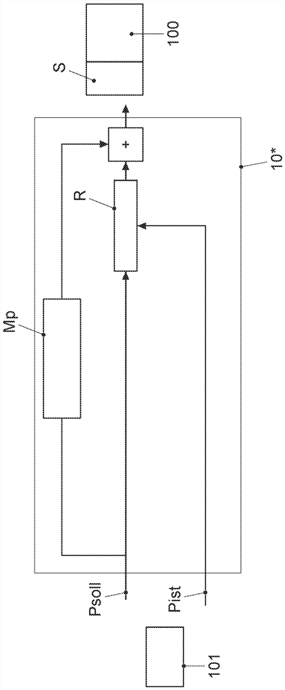
[0050] figure 1 The known control principle of the control variable in the operation of the turbocharger 100 is shown schematically, in which the boost P of the turbocharger 100 is regulated as the control variable.

[0051] The purpose of the regulation is to ensure that turbocharger 100 provides sufficient power at low exhaust gas flows and that its load limit, in particular its maximum permissible rotational speed N, is not exceeded as much as possible at high rotational speeds.

[0052] as in figure 1 As shown in , in the known case of boost regulation, engine control unit 10 * calculates a setpoint boost Psoll upstream of turbocharger 100 by means of model-based pilot control Mp. The model-based pre-control Mp is based on the known Euler turbine master equations.

[0053] A pressure sensor before the turb...


PUM


Abstract

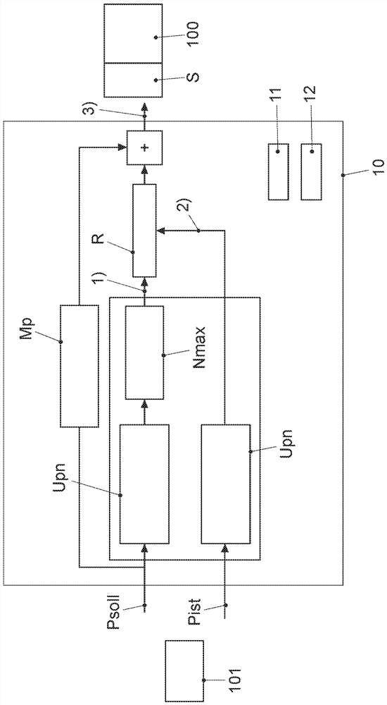
The invention relates to a method for regulating and limiting the rotational speed of a turbocharger, the invention relates to a method for controlling the rotational speed of a turbocharger (100) operatively connected to a compressor (101), the method comprises the following steps: 1) providing a setpoint value (Nsoll) for the rotational speed (N) of the turbocharger (100) on the basis of a model-based pre-control (Mp) for calculating a setpoint boost (Psoll) in front of the turbocharger (100); 2) determining an actual value (Nist) for the rotational speed (N) of the turbocharger (100); and 3) actuating an actuator (S) of the turbocharger (100) in order to balance a difference between the target value (Nsoll) for the rotational speed (N) of the turbocharger (100) and the actual value (Nist).

Description

technical field [0001] The following invention relates to a method for adjusting a control variable during operation of a turbocharger according to the independent method claim. Furthermore, the invention relates to a computer program product according to the independent product claim. Background technique [0002] A turbocharger is known which is arranged downstream of an internal combustion engine in the flow direction of the exhaust gas in order to convert the thermal and kinetic energy of the exhaust gas into mechanical power. This mechanical power can in turn be used to operate a compressor that supplies combustion air to the internal combustion engine. The faster the engine works, the faster the turbocharger spins. The faster the turbocharger spins, the more air is delivered by the compressor, which in turn accelerates the turbocharger through the increased volume of exhaust gases. At certain rotational speeds, however, the turbocharger reaches the load limit, that ...

Claims


Application Information

Patent Timeline
Patent Type & Authority Applications(China)
IPC IPC(8): F02D23/00F02B39/16
CPCF02D23/00F02B39/16F02D41/0007F02D2041/1433F02D2200/0406F02D41/1402F02B2039/168F02B2037/122F02B37/18F02B37/24Y02T10/12
Inventor S.海因肯M.卡拉布里亚A.戈隆齐S.米勒
Owner VOLKSWAGEN AG
Learn More