Anti-corrosion mud pump

A mud pump and body technology, applied in the field of anti-corrosion mud pumps, can solve the problems of improving the pump body, not being able to apply the plunger pump, and not being able to enhance the use efficiency of the pump body, and achieve the effect of improving efficiency and compact structure

Inactive Publication Date: 2016-04-13
NANYANG INST OF TECH
View PDF9 Cites 3 Cited by
  • Summary
  • Abstract
  • Description
  • Claims
  • Application Information

AI Technical Summary

Problems solved by technology

There is a handle on the upper end of the pump body, which is convenient for the operator to carry directly or lift the machine. The internal wires of the pump body extend from the upper end of the pump body to the outside, which can ensure that the wires are not easy to be crushed and broken, thereby ensuring the safety of the operator. The lower part of the pump body is set There is a support, which can make the pump body more convenient to operate when it is working. There is a plastic shell outside the pump body, and a waterproof film is wrapped outside the shell; although it can play a certain anti-corrosion effect, it is a conventional water pump and cannot Applied to plunger pumps; CN201129304Y discloses an anti-corrosion pump, including a check valve and a flow-passing component fixed below the check valve, characterized in that a layer of anti-corrosion is set on the surface of the flow-flow component contacting the water flow Corrosion-resistant and wear-resistant protective layer, the thickness of the protective layer is 0.03-0.3mm, which only adds a simple protective layer, which does not improve the pump body, nor can it enhance the use efficiency of the pump body. Replace it with a new pump body after a certain period of time, and there is no technical solution to this problem yet

Method used


Image

  • Anti-corrosion mud pump
  • Anti-corrosion mud pump
  • Anti-corrosion mud pump

Examples


Embodiment 2

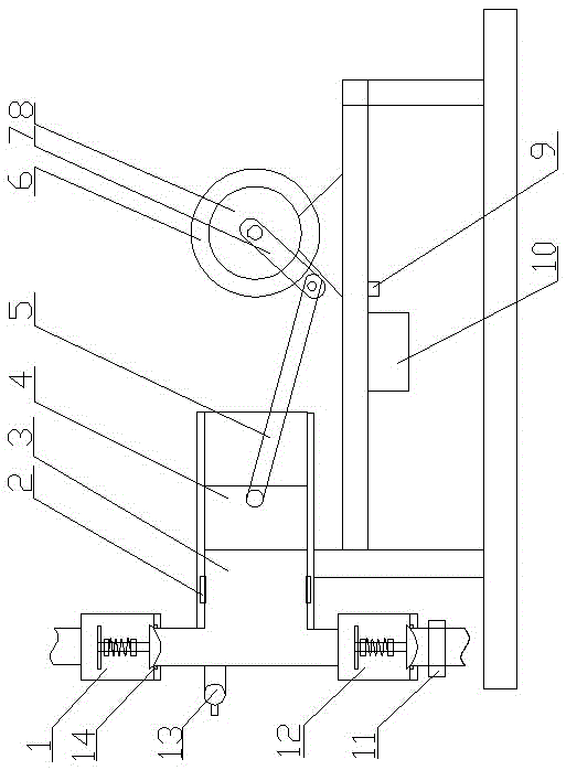
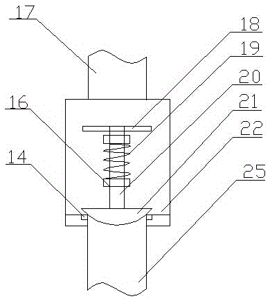
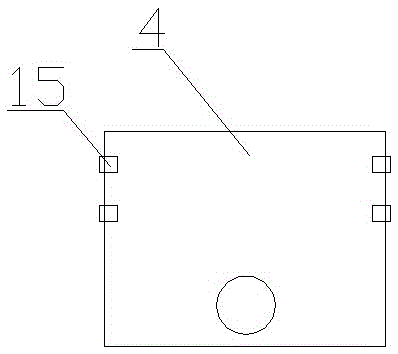
[0043] Embodiment 2: An anti-corrosion mud pump, including a pump body, a drive mechanism located at the rear of the pump body and a control mechanism connected to the drive mechanism, the pump body includes a cavity 3, a piston 4, a feed Valve 12 and discharge valve 1, the piston 4 is arranged in the cavity 3, the feed valve 12 and the discharge valve 1 are respectively arranged at the upper part and the lower part of the front end of the cavity 3, and the discharge valve 1 and the feed valve 12 are provided with a sealing module, and the inner wall of the cavity 3 is provided with a number of annular grooves 2, and a lubricating ring is arranged in the annular groove 2.

[0044] Described drive mechanism comprises drive motor 6, flywheel 8, crank 7 and connecting rod 5, and described drive motor 6 is connected with crank 7, and described crank 7 is connected with flywheel 8, and described crank 7 is movably connected with connecting rod 5 , the lubricating ring is a graphite...

Embodiment 3

[0052] Embodiment 3: An anti-corrosion mud pump, including a pump body, a drive mechanism located at the rear of the pump body and a control mechanism connected to the drive mechanism, the pump body includes a cavity 3, a piston 4, a feed Valve 12 and discharge valve 1, the piston 4 is arranged in the cavity 3, the feed valve 12 and the discharge valve 1 are respectively arranged at the upper part and the lower part of the front end of the cavity 3, and the discharge valve 1 and the feed valve 12 are provided with a sealing module, and the inner wall of the cavity 3 is provided with a number of annular grooves 2, and a lubricating ring is arranged in the annular groove 2.

[0053] Described drive mechanism comprises drive motor 6, flywheel 8, crank 7 and connecting rod 5, and described drive motor 6 is connected with crank 7, and described crank 7 is connected with flywheel 8, and described crank 7 is movably connected with connecting rod 5 , the lubricating ring is a graphite...

Embodiment 4

[0063] Embodiment 4: An anti-corrosion mud pump, including a pump body, a drive mechanism located at the rear of the pump body and a control mechanism connected to the drive mechanism, the pump body includes a cavity 3, a piston 4, a feed Valve 12 and discharge valve 1, the piston 4 is arranged in the cavity 3, the feed valve 12 and the discharge valve 1 are respectively arranged at the upper part and the lower part of the front end of the cavity 3, and the discharge valve 1 and the feed valve 12 are provided with a sealing module, and the inner wall of the cavity 3 is provided with a number of annular grooves 2, and a lubricating ring is arranged in the annular groove 2.

[0064] Described drive mechanism comprises drive motor 6, flywheel 8, crank 7 and connecting rod 5, and described drive motor 6 is connected with crank 7, and described crank 7 is connected with flywheel 8, and described crank 7 is movably connected with connecting rod 5 , the lubricating ring is a graphite...


PUM


Abstract

The invention discloses an anti-corrosion mud pump. The anti-corrosion mud pump comprises a pump body, a driving mechanism located behind the pump body and a control mechanism connected to the driving mechanism. The pump body comprises a cavity, a piston, a feed valve and a discharge valve, wherein the piston is arranged in the cavity, the feed valve is arranged at the upper part of the front end of the cavity, and the discharge valve is arranged at the lower part of the front end of the cavity. Sealing die blocks are arranged on the discharge valve and the feed valve. A plurality of annular grooves are formed in the inner wall of the cavity, and lubrication rings are arranged in the annular grooves. Layered sealing ring belts are arranged on the outer wall of piston rings so as to be capable of adapting to the cavity of a certain tolerance range, and air leaking or cylinder scoring can be avoided when the layered sealing ring belts move in the cavity; when the cylinder scoring phenomenon occurs, graphite can fill scratches through the joint effect of the graphite lubrication rings and the graphite in the layered sealing ring belts, and therefore the self-healing function can be realized.

Description

technical field [0001] The invention belongs to the technical field of engineering machinery, and in particular relates to an anti-corrosion mud pump. Background technique [0002] As we all know, mud pumps are widely used, but because mud pumps are easily affected by the environment, especially in humid and corrosive environments for a long time, conventional anti-corrosion mud pumps, because they only use paint for anti-corrosion , its service life is relatively short, and most of them will be scrapped after 1-2 years. It is difficult to meet the requirements of long-term use, which increases the capital investment of consumers in a disguised form. A kind of anti-corrosion water pump is disclosed in CN103671081A, including the pump body and the The water inlet and water outlet on the pump body are characterized in that a handle is provided at the upper end of the pump body, the internal wires of the pump body extend from the upper end of the pump body to the outside, the l...

Claims


Application Information

Patent Timeline
Patent Type & Authority Applications(China)
IPC IPC(8): F04B15/02F04B53/10F04B53/18F04B17/03
CPCF04B15/02F04B17/03F04B53/10F04B53/18
Inventor 薛党勤邱玉江陈红毅张林海马世榜
Owner NANYANG INST OF TECH
Why Eureka
Try Eureka