Electromagnetic valve

A solenoid valve and solenoid coil technology, applied in the field of solenoid valves, can solve the problems of difficulty in increasing the lift of the plunger and the lift of the spool and valve wear, so as to increase the flow rate, suppress the wear of the valve, and keep the pressure rising when the valve is opened. Effect

Pending Publication Date: 2020-09-22
FUJIKOKI MFG CO LTD
View PDF2 Cites 2 Cited by
  • Summary
  • Abstract
  • Description
  • Claims
  • Application Information

AI Technical Summary

Problems solved by technology

Therefore, the lift of the spool is determined by the lift of the plunger, which is determined by the overall length / body shape of the valve body or the minimum operating voltage, etc., so it is difficult to increase the lift of the plunger , that is, the lift of the spool
[0013] In addition, in the above-mentioned conventional solenoid valve, the valve core is directly subjected to the suction force of the plunger, and the valve core is strongly pressed against the valve seat when the valve is closed, so there is a possibility of valve wear caused by repeated operations.

Method used


Image

  • Electromagnetic valve
  • Electromagnetic valve
  • Electromagnetic valve

Examples


Embodiment Construction

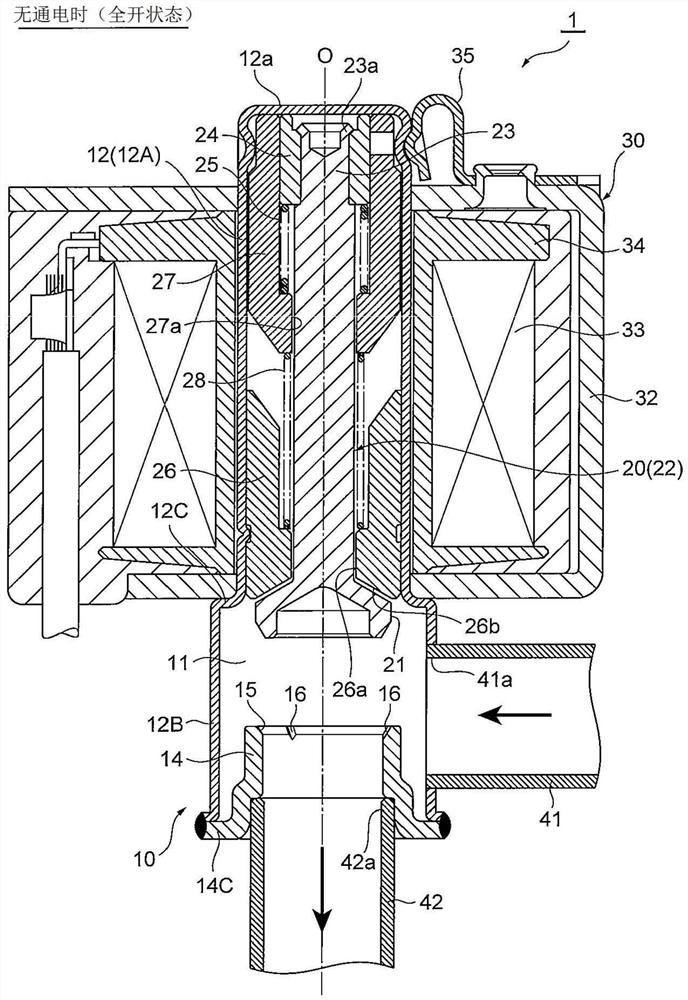
[0068] Below, while referring to the attached Figure 1 Embodiments of the present invention will be described.

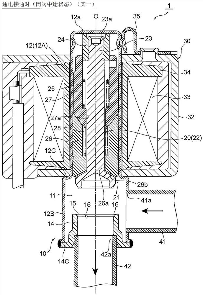
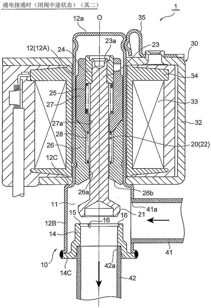
[0069] Figure 1 ~ Figure 4 It is a longitudinal sectional view showing one embodiment of the electromagnetic valve of the present invention, figure 1 Indicates when there is no power supply (full open state), figure 2 and image 3 Indicates that when the power is turned on (the halfway state of closing the valve), Figure 4 Indicates when the power is on (closed valve state).

[0070] In addition, in this specification, expressions indicating positions and directions such as up, down, left and right are for the convenience of referring to the drawings to avoid complicated descriptions, and do not necessarily refer to positions and directions in actual use.

[0071] Also, in each figure, gaps formed between components, isolation distances between components, and the like may be drawn larger or smaller than the size of each component for easier understanding o...


PUM


Abstract

The present invention provides an electromagnetic valve capable of increasing the lift amount of a valve body, increasing the flow rate, increasing the valve opening holding pressure, and suppressingvalve wear caused by repeated operation or the like without causing a change in performance such as the overall length/size of a valve body and the minimum operating voltage. A plunger (27) and a valve body (20) are disposed so as to be relatively movable in the vertical direction, and a valve opening spring (25) for urging the valve body (20) upward (in the valve opening direction) is provided between the plunger (27) and the valve body (20).

Description

technical field [0001] The present invention relates to a solenoid valve, and in particular, to a solenoid valve that contributes to an increase in the lift of a valve element, an increase in flow rate, an increase in valve opening holding pressure, and an improvement in durability. Background technique [0002] Conventionally, there is known a solenoid valve in which an opening and closing operation is performed by raising and lowering a valve element relative to a valve seat by magnetic force of a solenoid coil. [0003] For example, Patent Documents 1 and 2 disclose a so-called energization-closed (normally open) solenoid valve used as a dehumidification valve (drying valve) for throttling the refrigerant during dehumidification (drying) operation of an air conditioner. valve. [0004] The solenoid valve described in Patent Document 1 includes: a cylindrical valve body with one end closed; a plunger slidably accommodated on one end side of the valve body; part; the valv...

Claims


Application Information

Patent Timeline
Patent Type & Authority Applications(China)
IPC IPC(8): F16K1/00F16K1/32F16K31/06
CPCF16K1/00F16K1/32F16K31/0655
Inventor 津久井良辅
Owner FUJIKOKI MFG CO LTD
Why Eureka
Try Eureka