Eureka AIR delivers breakthrough ideas for toughest innovation challenges, trusted by R&D personnel around the world.

Air supplying and exhausting system capable of realizing waste gas purification and heat recovery

A heat recovery and exhaust gas purification technology, applied in the field of air supply and exhaust systems, can solve problems such as resource waste, indoor temperature drop, and exhaust gas emissions that are not up to standard, so as to avoid the decrease of comfort, avoid the drop of room temperature, and reduce environmental pollution.

Inactive Publication Date: 2020-09-22
安徽一洋实验设备有限公司
View PDF5 Cites 1 Cited by
  • Summary
  • Abstract
  • Description
  • Claims
  • Application Information

AI Technical Summary

Problems solved by technology

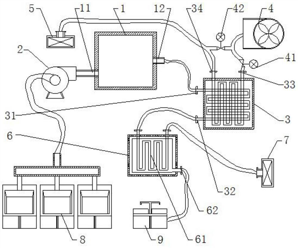
[0003] The experimental waste gas purification device used in the existing laboratory air supply and exhaust system often cannot purify the waste gas efficiently, and the waste gas discharge is not up to standard, causing environmental pollution. In addition, the heat generated by the waste gas purification cannot be effectively used, resulting in waste of resources
Especially in winter, the indoor heat and exhaust gas purification heating heat are discharged into the room with the exhaust gas. If no heated fresh air is sent into the room, the indoor temperature will drop sharply and affect the indoor comfort. If the outdoor lower temperature air is directly heated to the required temperature, will consume a lot of heating energy

Method used


Image

  • Air supplying and exhausting system capable of realizing waste gas purification and heat recovery
  • Air supplying and exhausting system capable of realizing waste gas purification and heat recovery

Examples


Embodiment Construction

[0018] Embodiments of the technical solutions of the present invention will be described in detail below in conjunction with the accompanying drawings. The following examples are only used to illustrate the technical solutions of the present invention more clearly, and therefore are only examples, rather than limiting the protection scope of the present invention.

[0019] In the description of the present application, it should be understood that the orientation or positional relationship indicated by the terms "upper", "lower", "left", "right", etc. is based on the orientation or positional relationship shown in the drawings, and is only for the purpose of It is convenient to describe the present invention and simplify the description, but does not indicate or imply that the device or element referred to must have a specific orientation, be constructed and operate in a specific orientation, and thus should not be construed as limiting the present invention.

[0020] Such as ...


PUM


Abstract

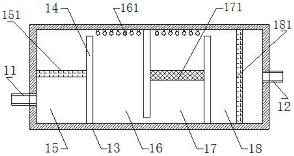
The invention provides an air supplying and exhausting system capable of realizing waste gas purification and heat recovery. The air supplying and exhausting system comprises a waste gas purificationdevice, an air exhausting fan, a hot air heat exchanger, an air inlet fan, air inlet shutters, a water storage box and air exhausting shutters; a waste gas inlet of the waste gas purification device communicates with the air exhausting fan; the waste gas purification device is used for catalyzing oxidation waste gas; the hot air heat exchanger is provided with a hot gas inlet, a hot gas outlet, anair inlet and an air outlet; the hot gas inlet communicates with a waste gas outlet of the waste gas purification device through a gas delivery pipeline; the air inlet communicates with the air inletfan through a gas delivery pipeline; the air outlet communicates with the air inlet shutters through a gas delivery pipeline; a heat exchange pipe is arranged inside the water storage box; the two ends of the heat exchange pipe communicate with the hot gas outlet and the air exhausting shutters; waste gas exchanges heat with water in the water storage box; and the heated water can be supplied forindoor use. According to the air supplying and exhausting system, the indoor experimental waste gas can be exhausted after being subjected to catalytic oxidation treatment, the air and the water areheated by heat of the waste gas, the heat of the waste gas is recycled effectively, and energy is saved.

Description

technical field [0001] The invention belongs to the technical field of exhaust air purification and air supply in chemical laboratories, and in particular relates to an air supply and exhaust system with exhaust gas purification and heat recovery. Background technique [0002] During the chemical laboratory, organic and / or inorganic waste gas will be generated along with the experiment. The waste gas needs to be discharged to the outside through the exhaust air purification device, and the fresh outdoor air is sent into the room by the air supply device. [0003] The experimental waste gas purification device used in the existing laboratory air supply and exhaust system often cannot purify the waste gas efficiently, and the waste gas discharge is not up to standard, causing environmental pollution. In addition, the heat generated by the waste gas purification cannot be effectively used, resulting in waste of resources. Especially in winter, the indoor heat and exhaust gas pu...

Claims


Application Information

Patent Timeline
Patent Type & Authority Applications(China)
IPC IPC(8): F24F7/007F24F13/30F24F13/15F24F12/00B01D46/12B01D53/86
CPCB01D46/12B01D53/86B01D2255/20707B01D2255/802B01D2259/804F24F7/007F24F12/001F24F13/15F24F13/30Y02B30/56
Inventor 刘春银
Owner 安徽一洋实验设备有限公司
Why Eureka
Eureka Blog
Learn More